LM3502ITL-44EV National Semiconductor, LM3502ITL-44EV Datasheet - Page 14
LM3502ITL-44EV
Manufacturer Part Number
LM3502ITL-44EV
Description
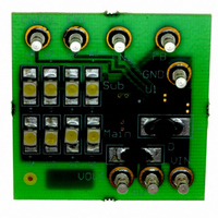
BOARD EVALUATION LM3502ITL-44
Manufacturer
National Semiconductor
Series
PowerWise®r
Specifications of LM3502ITL-44EV
Current - Output / Channel
9mA
Outputs And Type
2, Non-Isolated
Voltage - Output
44V
Features
Dual Display(s)
Voltage - Input
2.5 ~ 5.5V
Utilized Ic / Part
LM3502
Core Chip
LM3502
Topology
Boost
No. Of Outputs
1
Output Voltage
44V
Input Voltage
2.5V To 5.5V
Development Tool Type
Hardware - Eval/Demo Board
Lead Free Status / RoHS Status
Not applicable / Not applicable


www.national.com
Application Information
CONTINUOUS AND DISCONTINUOUS MODES OF
OPERATION
Since the LM3502 is a constant frequency pulse-width-
modulated step-up regulator, care must be taken to make
sure the maximum duty cycle specification is not violated.
The duty cycle equation depends on which mode of opera-
tion the LM3502 is in. The two operational modes of the
LM3502 are continuous conduction mode (CCM) and dis-
continuous conduction mode (DCM). Continuous conduction
mode refers to the mode of operation where during the
switching cycle, the inductor current never goes to and stays
at zero for any significant amount of time during the switch-
ing cycle. Discontinuous conduction mode refers to the
mode of operation where during the switching cycle, the
inductor current goes to and stays at zero for a significant
amount of time during the switching cycle. Figure 6 illus-
trates the threshold between CCM and DCM operation. In
Figure 6, the inductor current is right on the CCM/DCM
operational threshold. Using this as a reference, a factor can
be introduced to calculate when a particular application is in
CCM or DCM operation. R is a CCM/DCM factor we can use
to compute which mode of operation a particular application
is in. If R is ≥ 1, then the application is operating in CCM.
Conversely, if R is
The R factor inequalities are a result of the components that
make up the R factor. From Figure 6, the R factor is equal to
the average inductor current, I
inductor ripple current, ∆i
equation can be used to compute R factor:
<
1, the application is operating in DCM.
L
. Using Figure 6 the following
L
20131737
(avg), divided by half the
20131738
(Continued)
FIGURE 6. Inductor Current Waveform
14
V
V
Eff:
Fs:
I
L:
D:
∆i
I
For CCM operation, the duty cycle can be computed with:
D:
V
V
For DCM operation, the duty cycle can be computed with:
OUT
L
IN
OUT
OUT
IN
(avg): Average Inductor Current
L
:
:
:
:
:
: Output Voltage.
Duty Cycle for CCM Operation.
Input Voltage.
Input Voltage.
Output Voltage.
Efficiency of the LM3502.
Switching Frequency.
White LED Current/Load Current.
Inductance Magnitude/Inductor Value.
Duty Cycle for CCM Operation.
Inductor Ripple Current
20131743
20131741
20131739
20131742
20131740
20131736
Related parts for LM3502ITL-44EV
Image
Part Number
Description
Manufacturer
Datasheet
Request
R

Part Number:
Description:
IC LED DRVR WHT BCKLT 10MICROSMD
Manufacturer:
National Semiconductor
Datasheet:
Part Number:
Description:
IC LED DRVR WHT BCKLT 10MICROSMD
Manufacturer:
National Semiconductor
Datasheet:
Part Number:
Description:
IC LED DRVR WHT BCKLT 10MICROSMD
Manufacturer:
National Semiconductor
Datasheet:
Part Number:
Description:
IC LED DRVR WHT BCKLT 10USMD
Manufacturer:
National Semiconductor
Datasheet:

Part Number:
Description:
Step-Up Converter for White LED Applications
Manufacturer:
NSC [National Semiconductor]
Datasheet:

Part Number:
Description:
National Semiconductor [8-Bit D/A Converter]
Manufacturer:
National Semiconductor
Datasheet:
Part Number:
Description:
National Semiconductor [Media Coprocessor]
Manufacturer:
National Semiconductor
Datasheet:
Part Number:
Description:
Digitally Controlled Tone and Volume Circuit with Stereo Audio Power Amplifier, Microphone Preamp Stage and National 3D Sound
Manufacturer:
National Semiconductor
Datasheet:
Part Number:
Description:
Digitally Controlled Tone and Volume Circuit with Stereo Audio Power Amplifier, Microphone Preamp Stage and National 3D Sound
Manufacturer:
National Semiconductor
Datasheet:
Part Number:
Description:
AC97 Rev 2 Codec with Sample Rate Conversion and National 3D Sound
Manufacturer:
National Semiconductor
Part Number:
Description:
Manufacturer:
National Semiconductor
Datasheet:
Part Number:
Description:
Manufacturer:
National Semiconductor
Datasheet:
Part Number:
Description:
General Purpose, Low Voltage, Low Power, Rail-to-Rail Output Operational Amplifiers
Manufacturer:
National Semiconductor
Datasheet:
Part Number:
Description:
8-bit 20 MSPS flash A/D converter.
Manufacturer:
National Semiconductor
Datasheet: