LM3424BKBSTEVAL/NOPB National Semiconductor, LM3424BKBSTEVAL/NOPB Datasheet - Page 3
LM3424BKBSTEVAL/NOPB
Manufacturer Part Number
LM3424BKBSTEVAL/NOPB
Description
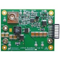
BOARD EVAL BUCK BOOST LM3424
Manufacturer
National Semiconductor
Series
PowerWise®r
Specifications of LM3424BKBSTEVAL/NOPB
Current - Output / Channel
1A
Outputs And Type
1, Non-Isolated
Features
Dimmable
Voltage - Input
10 ~ 70 V
Utilized Ic / Part
LM3424
Core Chip
LM3424
Topology
Buck-Boost
No. Of Outputs
1
Dimming Control Type
PWM / Analog
Development Tool Type
Hardware - Eval/Demo Board
Mcu Supported Families
LM3424 Family
Lead Free Status / RoHS Status
Lead free / RoHS Compliant
Voltage - Output
-
Other names
LM3424BKBSTEVAL


DAP
LM3424 Pin Descriptions
(21)
Pin
10
11
12
13
14
15
16
17
18
19
20
1
2
3
4
5
6
7
8
9
TSENSE
SLOPE
TGAIN
COMP
DDRV
Name
TREF
GATE
nDIM
GND
CSH
OVP
HSN
HSP
DAP
V
V
EN
RT
SS
V
IS
CC
IN
S
High-Side LED Current Sense
High-Side LED Current Sense
Thermal pad on bottom of IC
Temperature Foldback Gain
Dimming Gate Drive Output
Main Switch Current Sense
Temperature Sense Input
Internal Regulator Output
Over-Voltage Protection
Temperature Foldback
Slope Compensation
Current Sense High
Voltage Reference
Gate Drive Output
Resistor Timing
Compensation
Not DIM input
Input Voltage
Description
Reference
Soft-start
Negative
Positive
Ground
Enable
Bypass with 100 nF capacitor to GND as close to the device as possible in the
circuit board layout.
Connect to > 2.4V to enable the device or to < 0.8V for low power shutdown.
Connect a capacitor to GND to compensate control loop.
Connect a resistor to GND to set the signal current. Can also be used to analog
dim as explained in the Thermal Foldback / Analog Dimming section of the
datasheet.
Connect a resistor to GND to set the switching frequency. Can also be used
to synchronize external clock as explained in the Switching Frequency section
of the datasheet.
Connect a PWM signal for dimming as detailed in the PWM Dimming section
of the datasheet and/or a resistor divider from V
voltage lockout (UVLO). Turn-on threshold is 1.24V and hysteresis for turn-off
is provided by 20 µA current source.
Connect a capacitor to GND to extend start-up time.
Connect a resistor to GND to set the foldback slope.
Connect a resistor/ thermistor divider from V
explained in the Thermal Foldback / Analog Dimming section of the datasheet.
Connect a resistor divider from V
voltage.
2.45V reference for temperature foldback circuit and other external circuitry.
Connect to a resistor divider from V
(OVLO). Turn-off threshold is 1.24V and hysteresis for turn-on is provided by
20 µA current source.
Connect to gate of dimming MosFET.
Connect to DAP to provide proper system GND
Connect to gate of main switching MosFET.
Bypass with a 2.2 µF–3.3 µF, ceramic capacitor to GND.
Connect to the drain of the main N-channel MosFET switch for R
or to a sense resistor installed in the source of the same device.
Connect a resistor to GND to set slope of additional ramp.
Connect through a series resistor to the negative side of the LED current sense
resistor.
Connect through a series resistor to the positive side of the LED current sense
resistor.
Connect to GND and place 6 - 9 vias to bottom layer ground pour.
3
Application Information
S
to set the temperature foldback reference
O
to program output over-voltage lockout
S
to sense the temperature as
IN
to program input under-
www.national.com
DS-ON
sensing
Related parts for LM3424BKBSTEVAL/NOPB
Image
Part Number
Description
Manufacturer
Datasheet
Request
R

Part Number:
Description:
National Semiconductor [8-Bit D/A Converter]
Manufacturer:
National Semiconductor
Datasheet:
Part Number:
Description:
National Semiconductor [Media Coprocessor]
Manufacturer:
National Semiconductor
Datasheet:
Part Number:
Description:
Digitally Controlled Tone and Volume Circuit with Stereo Audio Power Amplifier, Microphone Preamp Stage and National 3D Sound
Manufacturer:
National Semiconductor
Datasheet:
Part Number:
Description:
Digitally Controlled Tone and Volume Circuit with Stereo Audio Power Amplifier, Microphone Preamp Stage and National 3D Sound
Manufacturer:
National Semiconductor
Datasheet:
Part Number:
Description:
AC97 Rev 2 Codec with Sample Rate Conversion and National 3D Sound
Manufacturer:
National Semiconductor
Part Number:
Description:
Manufacturer:
National Semiconductor
Datasheet:
Part Number:
Description:
Manufacturer:
National Semiconductor
Datasheet:
Part Number:
Description:
General Purpose, Low Voltage, Low Power, Rail-to-Rail Output Operational Amplifiers
Manufacturer:
National Semiconductor
Datasheet:
Part Number:
Description:
8-bit 20 MSPS flash A/D converter.
Manufacturer:
National Semiconductor
Datasheet:
Part Number:
Description:
Low Noise Quad Operational Amplifier
Manufacturer:
National Semiconductor
Datasheet:
Part Number:
Description:
Quad Differential Line Receivers
Manufacturer:
National Semiconductor
Datasheet:
Part Number:
Description:
Quad High Speed Trapezoidal? Bus Transceiver
Manufacturer:
National Semiconductor
Datasheet:
Part Number:
Description:
Dual Line Receiver
Manufacturer:
National Semiconductor
Datasheet:
Part Number:
Description:
TTL to 10k ECL Level Translator with Latch
Manufacturer:
National Semiconductor
Datasheet: