LP5526TLEV National Semiconductor, LP5526TLEV Datasheet - Page 8
LP5526TLEV
Manufacturer Part Number
LP5526TLEV
Description
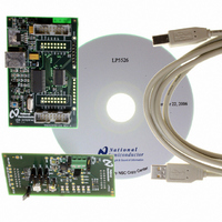
BOARD EVAL LP5526 LMU LED DRIVER
Manufacturer
National Semiconductor
Series
PowerWise®r
Specifications of LP5526TLEV
Current - Output / Channel
150mA
Outputs And Type
2 (25mA), 1 (150mA)
Voltage - Output
20 V
Features
Camera Flash, Dimmable, RGB Controller
Voltage - Input
3 ~ 5.5V
Utilized Ic / Part
LP5526
Lead Free Status / RoHS Status
Not applicable / Not applicable


www.national.com
Getting Started
The following instructions show how to use the LP5526 eval-
uation kit in default conditions with the USB interface board.
Please use the ESD protection (ground cable) to prevent any
unwanted damaging ESD events.
1.
2.
3.
4.
5.
6.
If you start the software first and then connect the USB cable,
the software may assume, that LPT interface is used. In that
case you can select the USB interface manually or close and
restart the software.
You should disconnect the USB cable from the computer al-
ways, when plugging in or removing the evaluation board from
the interface board and also when changing the supply
jumper settings. Otherwise the USB board may stop respond-
ing.
If the USB board is not responding or the software hangs up,
press the reset button on the USB board, or disconnect the
USB cable for 5 seconds.
If the evaluation software notices that the firmware on the
USB board needs to be updated, the software can propose
Check the jumpers and switches on the board according
to Figure 8. NOTE especially the power connection
jumpers: V
USB power should NOT be used unless you are sure that
you are not overloading USB supply. Using FLASH LEDs
can overload USB supply. V
to USB.
Plug in the evaluation board to the USB board. Connect
the USB cable to the evaluation board and the USB port
of your PC. When you plug in the USB board for the first
time, your operating system prompts you about “New
hardware found” and installs the USB driver
automatically. With Win95 and Win98 operating systems
you have to accept the installation and click “Next”
several times as the installation proceeds.
Copy the evaluation software and the support files to your
PC’s hard disk. Start the software by double-clicking its
icon.
Press Hardware Reset and USB Setup buttons to reset
the chip and the USB interface board.
Turn on the chip and the boost converter by clicking
stand-by and boost enable.
The Evaluation Kit is now ready to use and the chip can
be controlled through the PC-software.
BATT
is connected to external voltage source;
DD
and V
DDIO
are connected
8
automatic firmware updating. The new firmware will be in-
cluded in the evaluation kit software.
EASY START WITH BACKLIGHT DRIVING
1.
2.
3.
4.
5.
6.
7.
EASY START WITH FLASH DRIVING
1.
2.
3.
4.
5.
6.
7.
8.
9.
SPECIAL NOTES
IRGB resistor has set to 2,4 kΩ by default (when J26 is set),
which limits the Flash current to 150 mA max. Typically boost
can provide 150 mA (V
Attach the USB cable.
Attach external voltage source for V
max current).
Launch the SW (LP5526eval.exe). You should get a
control window up.
Press USB Setup.
Go to the File open menu and select the
"LP5526wled_on.nsc" file and open it; this will light up the
sub and main backlight LED’s.
Go to the ‘Backlight’ tab.
Try to adjust brightness of main and sub backlight LEDs,
together and separately.
Attach USB cable.
Attach external voltage source for VBATT (3.60V, 1.5A
max current).
Ensure all jumpers are in right position for Flash LED
driving.
Launch the SW (LP5526eval.exe).
Press USB Setup.
Go to File open menu and select the
‘LP5526flash_enabled.nsc’ file and open it; this will light
up the Flash LED in Pre-Flash/Torch mode.
Go to ‘Color LEDs’ tab.
Press Flash button to trigger flash.
To initiate new flash:
— Disable ‘Flash enable’ bit, and all safety bits.
— Enable first ‘Flash enable’ bit and then all safety bits.
— Flash LED should be now on Pre-Flash/Torch mode
with safety function on, and ready for Flash triggering
by pressing the ‘Flash’ button.
BATT
= 3.6V, V
BOOST
BATT
= 20V).
(3.60V, 1.5A
Related parts for LP5526TLEV
Image
Part Number
Description
Manufacturer
Datasheet
Request
R

Part Number:
Description:
National Semiconductor [8-Bit D/A Converter]
Manufacturer:
National Semiconductor
Datasheet:
Part Number:
Description:
National Semiconductor [Media Coprocessor]
Manufacturer:
National Semiconductor
Datasheet:
Part Number:
Description:
Digitally Controlled Tone and Volume Circuit with Stereo Audio Power Amplifier, Microphone Preamp Stage and National 3D Sound
Manufacturer:
National Semiconductor
Datasheet:
Part Number:
Description:
Digitally Controlled Tone and Volume Circuit with Stereo Audio Power Amplifier, Microphone Preamp Stage and National 3D Sound
Manufacturer:
National Semiconductor
Datasheet:
Part Number:
Description:
AC97 Rev 2 Codec with Sample Rate Conversion and National 3D Sound
Manufacturer:
National Semiconductor
Part Number:
Description:
Manufacturer:
National Semiconductor
Datasheet:
Part Number:
Description:
Manufacturer:
National Semiconductor
Datasheet:
Part Number:
Description:
General Purpose, Low Voltage, Low Power, Rail-to-Rail Output Operational Amplifiers
Manufacturer:
National Semiconductor
Datasheet:
Part Number:
Description:
8-bit 20 MSPS flash A/D converter.
Manufacturer:
National Semiconductor
Datasheet:
Part Number:
Description:
Low Noise Quad Operational Amplifier
Manufacturer:
National Semiconductor
Datasheet:
Part Number:
Description:
Quad Differential Line Receivers
Manufacturer:
National Semiconductor
Datasheet:
Part Number:
Description:
Quad High Speed Trapezoidal? Bus Transceiver
Manufacturer:
National Semiconductor
Datasheet:
Part Number:
Description:
Dual Line Receiver
Manufacturer:
National Semiconductor
Datasheet:
Part Number:
Description:
TTL to 10k ECL Level Translator with Latch
Manufacturer:
National Semiconductor
Datasheet: