NCP1421LEDEVB ON Semiconductor, NCP1421LEDEVB Datasheet - Page 7
NCP1421LEDEVB
Manufacturer Part Number
NCP1421LEDEVB
Description
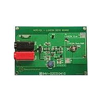
EVAL BOARD FOR NCP1421LED
Manufacturer
ON Semiconductor
Specifications of NCP1421LEDEVB
Design Resources
NCP1421LEDEVB BOM NCP1421LEDEVB Schematic NCP1421LEDEVB Gerber Files
Current - Output / Channel
600mA
Outputs And Type
1, Non-Isolated
Voltage - Output
500 ~ 700 mV
Voltage - Input
3.6V
Utilized Ic / Part
NCP1421
Core Chip
NCP1421
Topology
Boost
No. Of Outputs
1
Output Current
600mA
Development Tool Type
Hardware - Eval/Demo Board
Mcu Supported Families
NCP1421
Lead Free Status / RoHS Status
Lead free / RoHS Compliant
Features
-
Lead Free Status / Rohs Status
Lead free / RoHS Compliant
For Use With/related Products
NCP1421LED
Other names
NCP1421LEDEVBOS


12.5
−10
7.5
5.0
2.5
10
−5
50
40
30
20
10
15
10
5
0
0
10
1.5
1.5
Figure 16. Battery Input Voltage vs. Output Ripple
Figure 18. No Load Operating Current vs. Input
Figure 14. Output Voltage Change vs. Load
V
L = 5.6 mH
C
C
T
A
OUT
IN
OUT
V
V
L = 6.8 mH
C
C
T
= 25_C
A
IN
OUT
IN
OUT
= 22 mF
2.0
= 25_C
= 2.5 V
= 22 mF
= 3.3 V
= 22 mF
OUTPUT LOADING CURRENT, I
1.7
INPUT VOLTAGE AT OUT PIN, V
= 3.3 V
= 22 mF
BATTERY INPUT VOLTAGE, V
2.5
Voltage at OUT Pin
1.9
3.0
Current
Voltage
100
3.5
500 mA
300 mA
100 mA
TYPICAL OPERATING CHARACTERISTICS
2.1
4.0
LOAD
BATT
OUT
V
V
2.3
IN
IN
/V
/mA
/V
= 2.5 V
= 2.0 V
4.5
http://onsemi.com
1000
NCP1421
2.5
5.0
7
−10
10
−5
5
0
10
Upper Trace: Voltage at LBI Pin, 1.0 V/Division
Lower Trace: Voltage at LBO Pin, 1.0 V/Division
Upper Trace: Input Voltage Waveform, 1.0 V/Division
Lower Trace: Output Voltage Waveform, 2.0 V/Division
V
L = 5.6 mH
C
C
T
A
OUT
IN
OUT
Figure 15. Output Voltage Change vs. Load
= 25_C
= 22 mF
Figure 19. Startup Transient Response
= 5.0 V
= 22 mF
OUTPUT LOADING CURRENT, I
Figure 17. Low Battery Detect
Current
100
V
IN
= 1.5 V
V
V
I
LOAD
IN
OUT
LOAD
= 2.5 V
V
= 5.0 V
= 10 mA
IN
V
IN
/mA
= 2.5 V
= 3.3 V
1000
Related parts for NCP1421LEDEVB
Image
Part Number
Description
Manufacturer
Datasheet
Request
R

Part Number:
Description:
600 Ma Sync-rect Pfm Step-up Dc-dc Converter Step-up Dc-dc Converter With True-cutoff And Ring-killer
Manufacturer:
ON Semiconductor
Datasheet:

Part Number:
Description:
EVAL BOARD FOR NCP1421
Manufacturer:
ON Semiconductor
Datasheet:
Part Number:
Description:
ON Semiconductor [VOLTAGE REGULATOR]
Manufacturer:
ON Semiconductor
Datasheet:
Part Number:
Description:
357-036-542-201 CARDEDGE 36POS DL .156 BLK LOPRO
Manufacturer:
ON Semiconductor
Datasheet:
Part Number:
Description:
357-036-542-201 CARDEDGE 36POS DL .156 BLK LOPRO
Manufacturer:
ON Semiconductor
Datasheet:
Part Number:
Description:
357-036-542-201 CARDEDGE 36POS DL .156 BLK LOPRO
Manufacturer:
ON Semiconductor
Datasheet:
Part Number:
Description:
357-036-542-201 CARDEDGE 36POS DL .156 BLK LOPRO
Manufacturer:
ON Semiconductor
Datasheet:
Part Number:
Description:
357-036-542-201 CARDEDGE 36POS DL .156 BLK LOPRO
Manufacturer:
ON Semiconductor
Datasheet:
Part Number:
Description:
357-036-542-201 CARDEDGE 36POS DL .156 BLK LOPRO
Manufacturer:
ON Semiconductor
Datasheet:
Part Number:
Description:
357-036-542-201 CARDEDGE 36POS DL .156 BLK LOPRO
Manufacturer:
ON Semiconductor
Datasheet:
Part Number:
Description:
357-036-542-201 CARDEDGE 36POS DL .156 BLK LOPRO
Manufacturer:
ON Semiconductor
Datasheet:
Part Number:
Description:
357-036-542-201 CARDEDGE 36POS DL .156 BLK LOPRO
Manufacturer:
ON Semiconductor
Datasheet:
Part Number:
Description:
357-036-542-201 CARDEDGE 36POS DL .156 BLK LOPRO
Manufacturer:
ON Semiconductor
Datasheet:
Part Number:
Description:
Manufacturer:
ON Semiconductor
Datasheet: