SOT89-3EV-VREG Microchip Technology, SOT89-3EV-VREG Datasheet - Page 11
SOT89-3EV-VREG
Manufacturer Part Number
SOT89-3EV-VREG
Description
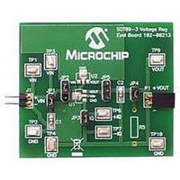
BOARD EVAL SOT89-3 VOLTAGE REG
Manufacturer
Microchip Technology
Datasheets
1.SOT89-3EV-VREG.pdf
(24 pages)
2.SOT89-3EV-VREG.pdf
(26 pages)
3.SOT89-3EV-VREG.pdf
(28 pages)
4.SOT89-3EV-VREG.pdf
(22 pages)
5.SOT89-3EV-VREG.pdf
(22 pages)
Specifications of SOT89-3EV-VREG
Channels Per Ic
1 - Single
Regulator Type
Positive Fixed
Board Type
Partially Populated
Utilized Ic / Part
SOT-89-3 Package
Silicon Manufacturer
Microchip
Application Sub Type
Voltage Regulator
Kit Application Type
Power Management - Voltage Regulator
Silicon Core Number
MCP1700A, MCP1701A, MCP1702, MCP1703
Lead Free Status / RoHS Status
Lead free / RoHS Compliant
Current - Output
-
Voltage - Output
-
Voltage - Input
-
Operating Temperature
-
Lead Free Status / Rohs Status
Lead free / RoHS Compliant


2.1
2.2
2.3
© 2009 Microchip Technology Inc.
INTRODUCTION
FEATURES
GETTING STARTED
Chapter 2. Installation and Operation
The SOT89-3 Voltage Regulator Evaluation Board is designed to be used to facilitate
evaluation of Microchip’s voltage regulators or to be used as a standalone voltage
regulator board. Jumpers have been placed on the board to facilitate testing of specific
voltage regulator parameters.
The SOT89-3 Voltage Regulator Evaluation Board kit comes with a 1 µF ceramic input
and output capacitor soldered to the board. The board has one unpopulated resistor
location that may be used for a load.
The SOT89-3 Voltage Regulator Evaluation Board has the following features:
• Input and Output headers for future connection to Line Step and Load Step
• Ample testpoints to attach multimeters, power supplies, and loads.
• Jumper to select ground current measurement
• Jumper to connect output load resistor
• Jumper to connect input capacitor to circuit
• Jumper to select one of two device pinouts
The SOT89-3 Voltage Regulator Evaluation Board is fully assembled and tested. All
that is required for operating is a user supplied voltage regulator and a supply voltage
source. Some of the tests that may be completed using the SOT89-3 Voltage Regulator
Evaluation Board shall now be described.
2.3.1
For all tests, JP2 and JP5 must be set to select the desired device and footprint.
JP2 - connect pins
JP5 - connect pins
modules
Jumpers
Device Pinout Selection (For All Tests)
EVALUATION BOARD USER’S GUIDE
SOT89-3 VOLTAGE REGULATOR
U1 Footprint
2-3
2-3
U2 Footprint
1-2
1-2
DS51796A-page 7
Related parts for SOT89-3EV-VREG
Image
Part Number
Description
Manufacturer
Datasheet
Request
R

Part Number:
Description:
Manufacturer:
Infineon Technologies
Datasheet:
Part Number:
Description:
Manufacturer:
Infineon Technologies
Datasheet:
Part Number:
Description:
Manufacturer:
Infineon Technologies
Datasheet:
Part Number:
Description:
Manufacturer:
Infineon Technologies
Datasheet:
Part Number:
Description:
Manufacturer:
Infineon Technologies
Datasheet:
Part Number:
Description:
Manufacturer:
Infineon Technologies
Datasheet:
Part Number:
Description:
Manufacturer:
Infineon Technologies
Datasheet:
Part Number:
Description:
Manufacturer:
Infineon Technologies
Datasheet:
Part Number:
Description:
Manufacturer:
Infineon Technologies
Datasheet:
Part Number:
Description:
Manufacturer:
Infineon Technologies
Datasheet:
Part Number:
Description:
Manufacturer:
Infineon Technologies
Datasheet:
Part Number:
Description:
Manufacturer:
Infineon Technologies
Datasheet: