NCP565VADJEVB ON Semiconductor, NCP565VADJEVB Datasheet
NCP565VADJEVB
Manufacturer Part Number
NCP565VADJEVB
Description
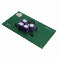
EVAL BOARD FOR NCP565VADJ
Manufacturer
ON Semiconductor
Specifications of NCP565VADJEVB
Design Resources
NCP565 ADJ Demo Board BOM NCP565VADJEVB Gerber Files NCP565 ADJ Demo Board Schematic
Channels Per Ic
1 - Single
Voltage - Output
3.3V
Current - Output
1.5A
Voltage - Input
5V
Regulator Type
Positive Fixed
Board Type
Fully Populated
Utilized Ic / Part
NCP565
Lead Free Status / RoHS Status
Lead free / RoHS Compliant
Operating Temperature
-
Lead Free Status / Rohs Status
Lead free / RoHS Compliant
For Use With/related Products
NCP565VADJ
Other names
NCP565VADJEVBOS
Test Procedures for NCP565 ADJ Demonstration Board
h
08/25/2003
The adjustable output voltage for this demo board is set at 3.3V based on the BOM. If
other voltage value is desired, please choose different resistance values for R1 and R2.
The output voltage is set according to the formula:
The adjust pin current, Iadj, is typically 30nA and normally much lower than the current
flowing through R1 and R2, thus it generates a small output voltage error that can
usually be ignored.
Test procedures for NCP565 ADJ demonstration board
1. Test equipments:
a. DC power supply
b. 2 multi-meters
c. Electrical Load
d. Oscilloscope
2. Test procedures:
a. Connect the demo board as shown in Figure 1
Vout
Vin
A
A
V
Iload
DC
Gnd
Figure 1: NCP565 Test Setup
b. Turn on the power supply to 5V and no load current. Check Vout is about 3.3V. If
there is big difference from 3.3V, please check R1 and R2 and make sure they are in the
right position.
c. Adjust load current from 10mA to 1.5A and use the scope to see NCP565 Pin 5(ADJ
pin) voltage. Make sure it is in the range of 0.882V~0.918V (typical value is 0.9V) and no
oscillation on it.
Related parts for NCP565VADJEVB
Image
Part Number
Description
Manufacturer
Datasheet
Request
R

Part Number:
Description:
ON Semiconductor [VOLTAGE REGULATOR]
Manufacturer:
ON Semiconductor
Datasheet:
Part Number:
Description:
357-036-542-201 CARDEDGE 36POS DL .156 BLK LOPRO
Manufacturer:
ON Semiconductor
Datasheet:
Part Number:
Description:
357-036-542-201 CARDEDGE 36POS DL .156 BLK LOPRO
Manufacturer:
ON Semiconductor
Datasheet:
Part Number:
Description:
357-036-542-201 CARDEDGE 36POS DL .156 BLK LOPRO
Manufacturer:
ON Semiconductor
Datasheet:
Part Number:
Description:
357-036-542-201 CARDEDGE 36POS DL .156 BLK LOPRO
Manufacturer:
ON Semiconductor
Datasheet:
Part Number:
Description:
357-036-542-201 CARDEDGE 36POS DL .156 BLK LOPRO
Manufacturer:
ON Semiconductor
Datasheet:
Part Number:
Description:
357-036-542-201 CARDEDGE 36POS DL .156 BLK LOPRO
Manufacturer:
ON Semiconductor
Datasheet:
Part Number:
Description:
357-036-542-201 CARDEDGE 36POS DL .156 BLK LOPRO
Manufacturer:
ON Semiconductor
Datasheet:
Part Number:
Description:
357-036-542-201 CARDEDGE 36POS DL .156 BLK LOPRO
Manufacturer:
ON Semiconductor
Datasheet:
Part Number:
Description:
357-036-542-201 CARDEDGE 36POS DL .156 BLK LOPRO
Manufacturer:
ON Semiconductor
Datasheet:
Part Number:
Description:
357-036-542-201 CARDEDGE 36POS DL .156 BLK LOPRO
Manufacturer:
ON Semiconductor
Datasheet:
Part Number:
Description:
Manufacturer:
ON Semiconductor
Datasheet:
Part Number:
Description:
Manufacturer:
ON Semiconductor
Datasheet:
Part Number:
Description:
Manufacturer:
ON Semiconductor
Datasheet: