SOT23-3EV-VREG Microchip Technology, SOT23-3EV-VREG Datasheet - Page 12
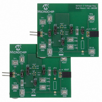
SOT23-3EV-VREG
Manufacturer Part Number
SOT23-3EV-VREG
Description
BOARD EVAL VOLT REG SOT23-3
Manufacturer
Microchip Technology
Datasheet
1.SOT23-3EV-VREG.pdf
(22 pages)
Specifications of SOT23-3EV-VREG
Channels Per Ic
1 - Single
Board Type
Partially Populated
Utilized Ic / Part
SOT-23-3 Package
Silicon Manufacturer
Microchip
Application Sub Type
Voltage Regulator
Kit Application Type
Power Management - Voltage Regulator
Silicon Core Number
MCP1701A, MCP1702, MCP1703
Kit Contents
Board
Lead Free Status / RoHS Status
Lead free / RoHS Compliant
Current - Output
-
Voltage - Output
-
Voltage - Input
-
Operating Temperature
-
Regulator Type
-
Lead Free Status / Rohs Status
Lead free / RoHS Compliant


SOT23-3 Voltage Regulator Evaluation Board User’s Guide
DS51785A-page 8
2.3.2
When measuring ground current, jumper JP3 should be removed, otherwise leave
jumper JP3 on. To measure ground current, perform the following steps:
1. Add the desired load resistor to R5.
2. Remove jumpers JP3 and JP4.
3. Connect an ammeter across testpoints TP6(+) and TP7(-). Select the
4. Connect a voltmeter across testpoints TP9(+) and TP10(-).
5. Add jumper JP1.
6. Apply source voltage to testpoints TP1(+) and TP2(-).
7. Verify that the voltage across testpoints TP9 and TP10 is within the expected
8. Read the Ground Current directly from the ammeter connected to testpoints TP6
9. Vary the input voltage to obtain data for ground current versus input voltage.
10. Add the load selection jumper, JP4.
11. Read the Ground Current directly from the ammeter connected to testpoints TP6
12. The data collected will be the “ground current” versus load current.
2.3.3
R5 is used to set the desired load value. One choice is to set R5 to the minimum current
wanted for testing.
2.3.4
Dynamic Line Step response may be evaluated by connecting an electronically
switched input voltage to testpoints TP1(+) and TP2(-), or to connector J1. An
oscilloscope is connected to TP3(Ch1 Trigger), TP9(Ch2) and TP10(Gnd). An
appropriate load is selected using R5 and JP4. The input voltage is then electronically
switched from a low voltage to a high voltage. The corresponding voltage waveform
data of the voltage regulator response is captured by the oscilloscope. Microchip will
be offering a Line Step module, part #102-00196, that connects directly to
connector J1. The Line Step module will be capable of switching between two voltage
levels that the user supplies.
2.3.5
Dynamic Load Step response may be evaluated by connecting an electronically
switched load to testpoints TP9(+) and TP10(-) or to connector P1. An oscilloscope is
connected to the electronic load switch signal (Ch1 Trigger) and to TP9 (Ch2) and
TP10 (Gnd). The load is then electronically switched from a high resistance to a lower
one. The corresponding voltage waveform data of the voltage regulator response is
captured by the oscilloscope. Microchip will be offering a Load Step module, part
#102-00197, that connects directly to connector P1. The Load Step module will have
several selectable load values populated on board to cover a wide range of loads. The
load will have the ability to be electronically or manually switched.
appropriate meter scale for the device that is being evaluated.
range of the tested device.
and TP7.
With no load attached to the output of the voltage regulator, the measured
“ground current” is also called the “quiescent current” of the regulator.
and TP7.
Ground Current and Quiescent Current
Load Resistance
Line Step
Load Step
© 2008 Microchip Technology Inc.
Related parts for SOT23-3EV-VREG
Image
Part Number
Description
Manufacturer
Datasheet
Request
R


Part Number:
Description:
SOT23/E/ECONRST 3.3V 5% CMOS OUT SOT23 T&R
Manufacturer:
Maxim Integrated Products
Datasheet:
Part Number:
Description:
SOT23-6/A�/20MBPS +3.3V SOT23 RS-485/RS-422 TRANSMITTERS
Manufacturer:
Maxim Integrated Products
Datasheet:
Part Number:
Description:
SOT23-8/A�/Low-Voltage, SOT23, �P Supervisors
Manufacturer:
Maxim Integrated Products
Part Number:
Description:
SOT23/E/ECONORST 3.3V-10% W/PBRST SOT23 T&R
Manufacturer:
Maxim Integrated Products

Part Number:
Description:
SOT23, Low-Power uP Supervisory Circuits with Battery Backup and Chip-Enable Gating
Manufacturer:
Maxim Integrated Products
Datasheet:
Part Number:
Description:
SOT23, Low-Power uP Supervisory Circuits with Battery Backup and Chip-Enable Gating
Manufacturer:
Maxim Integrated Products
