AD8332-EVALZ Analog Devices Inc, AD8332-EVALZ Datasheet

BOARD EVAL FOR AD8332

AD8332-EVALZ

Manufacturer Part Number
AD8332-EVALZ
Description
BOARD EVAL FOR AD8332
Manufacturer
Analog Devices Inc
Series
X-AMP®r
Datasheets

Specifications of AD8332-EVALZ

Channels Per Ic
1 - Single
Amplifier Type
Variable Gain
Output Type
Differential
Slew Rate
1100 V/µs
-3db Bandwidth
100MHz
Current - Output / Channel
45mA
Operating Temperature
-40°C ~ 85°C
Current - Supply (main Ic)
27.5mA
Voltage - Supply, Single/dual (±)
4.5 V ~ 5.5 V
Board Type
Fully Populated
Utilized Ic / Part
AD8332
Silicon Manufacturer
Analog Devices
Application Sub Type
Variable Gain Amplifier
Kit Application Type
Amplifier
Silicon Core Number
AD8332
Kit Contents
Board
Lead Free Status / RoHS Status
Lead free / RoHS Compliant
GENERAL DESCRIPTION
The AD8332-EVALZ is a platform for the test and evaluation of
the
assembled and tested, and users only need to connect the signal
and VGAIN sources to a single 5 V power supply. Figure 1 is a
photograph of the component side of the board, and Figure 2 is
the schematic.
USER-SUPPLIED OPTIONAL COMPONENTS
The board is built and tested using the components shown in
black in Figure 2. Provisions are made for optional components
(shown in gray) that can be installed for testing at the user’s
discretion. The default LNA input impedance is 50 Ω to match
various signal generators and network analyzers. Input impedances
up to 6 kΩ are realized by changing values of RFBx and CSHx.
Consult the
feature.
Rev. D
Evaluation boards are only intended for device evaluation and not for production purposes.
Evaluation boards are supplied “as is” and without warranties of any kind, express, implied, or
statutory including, but not limited to, any implied warranty of merchantability or fitness for a
particular purpose. No license is granted by implication or otherwise under any patents or other
intellectual property by application or use of evaluation boards. Information furnished by Analog
Devices is believed to be accurate and reliable. However, no responsibility is assumed by Analog
Devices for its use, nor for any infringements of patents or other rights of third parties that may result
from its use. Analog Devices reserves the right to change devices or specifications at any time
without notice. Trademarks and registered trademarks are the property of their respective owners.
Evaluation boards are not authorized to be used in life support devices or systems.
AD8332
Figure 1. AD8332-EVALZ Photo of Component Side
variable gain amplifier (VGA). The board is shipped
AD8332
data sheet for more details on this circuit
Dual VGA, Ultralow Noise Preamplifier, and
Programmable R
One Technology Way, P.O. Box 9106, Norwood, MA 02062-9106, U.S.A.
Tel: 781.329.4700
Fax: 781.461.3113
For reference, Table 1 lists the common input impedance values
and corresponding adjustments. The board is designed for
0603-size, surface-mount components.
Table 1. LNA External Component Values for Common
Source Impedances
R
50
75
100
200
500
6 k
SMA connectors, S2, S3, S6, and S7, are provided for access to
the LNA outputs or the VGA inputs. If the LNA is used alone,
0.1 μF coupling capacitors can be installed at locations C5, C9,
C23, and C24. Resistors of 68 Ω to 100 Ω can be required if the
load capacitances, as seen by the LNA outputs, are larger than
approximately 10 pF.
A resistor can be inserted at RCLMP if output clamping
is desired. The peak-to-peak clamping level is adjusted by
installing one of the standard 1% resistor values listed in the
AD8332
A high frequency differential probe connected to the 2-pin
headers VOx is the preferred method to observe a waveform
at the VGA output. A typical setup is shown in Figure 3. Single-
ended loads can be connected directly via the board edge SMA
connectors. Note that the
237 Ω resistors; therefore, be sure to compensate for attenuation if
low impedances are connected to the output SMAs.
MEASUREMENT SETUP
The basic board connections for measuring bandwidth are
shown in Figure 3. A 5 V, 100 mA (minimum) power supply is
required, and a low noise voltage reference supply is required
for VGAIN.
IN
(Ω)
data sheet.
RFBx (Ω, Std 1% Value)
274
412
562
1.13 k
3.01 k
©2003–2007 Analog Devices, Inc. All rights reserved.
IN
AD8332
Evaluation Board
AD8332-EVALZ
output amplifier is buffered with
www.analog.com
CSHx (pF)
22
12
8
1.2
None
None

Related parts for AD8332-EVALZ

AD8332-EVALZ Summary of contents

Page 1

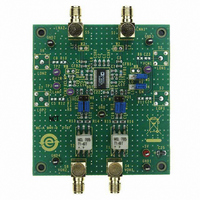
... GENERAL DESCRIPTION The AD8332-EVALZ is a platform for the test and evaluation of the AD8332 variable gain amplifier (VGA). The board is shipped assembled and tested, and users only need to connect the signal and VGAIN sources to a single 5 V power supply. Figure photograph of the component side of the board, and Figure 2 is the schematic ...

Page 2

... AD8332-EVALZ TABLE OF CONTENTS General Description ......................................................................... 1 User-Supplied Optional Components ........................................... 1 Measurement Setup.......................................................................... 1 Revision History ............................................................................... 2 Evaluation Board Schematic ........................................................... 3 Board Layout and Parts List........................................................ 4 REVISION HISTORY 11/07—Rev Rev. D Changes to Figure 1.......................................................................... 1 Changes to Figure 2.......................................................................... 3 Changes to Figure 3.......................................................................... 4 Changes to Figure 4 and Figure 9................................................... 5 Changes to Table 2 and Ordering Guide ....................................... 6 5/06— ...

Page 3

... L3 120nH FB VOH2 VOH1 100Ω VOL2 13 VOL1 16 R8 100Ω L4 120nH FB COMM VPSV 14 15 C22 0.1µF Figure 2. AD8332-EVALZ Schematic Rev Page AD8332-EVALZ C1 0.1µF C3 CSH1 L2 0.1µF LNA1 22pF 120nH FB CFB1 CAL1 18nF +5VLNA C7 0.1µF S2 LON1 C23 R9 W9 ...

Page 4

... AD8332-EVALZ SUPPLY FOR VGAIN BOARD LAYOUT AND PARTS LIST The evaluation board circuitry uses four conductor layers. The two inner layers are power and ground planes, and all interconnecting circuitry is located on the outer layers. Figure 5, Figure 6, Figure 7, and Figure 8 illustrate the copper patterns. ...

Page 5

... EVALUATION BOARD PCB LAYERS Figure 4. AD8332-EVALZ Assembly Figure 5. Primary Side Copper Figure 6. Secondary Side Copper Figure 7. Ground Plane Figure 8. Power Plane Figure 9. Component Side Silkscreen Rev Page AD8332-EVALZ ...

Page 6

... AD8332-EVALZ ORDERING INFORMATION PARTS LIST Table 2. Qty. Name Description 8 Inductor Ferrite Bead, 120 nH, 0603 2 Resistor SM, 274 Ω, 1%, 1/10 W, 0603 4 Resistor SM, 237 Ω, 1%, 1/10 W, 0603 4 Resistor SM, 100 Ω, 1%, 1/16 W, 0603 2 Capacitor SM, 18 nF, 10 0603 18 Capacitor SM, 0.1 μF, 10%, 0603 1 Capacitor SM 0603 2 Capacitor ...

Page 7

... NOTES Rev Page AD8332-EVALZ ...

Page 8

... AD8332-EVALZ NOTES ©2003–2007 Analog Devices, Inc. All rights reserved. Trademarks and registered trademarks are the property of their respective owners. EB03635-0-11/07(D) Rev Page ...

Related keywords