AD8336-EVALZ Analog Devices Inc, AD8336-EVALZ Datasheet - Page 22
AD8336-EVALZ
Manufacturer Part Number
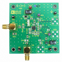
AD8336-EVALZ
Description
BOARD EVALUATION FOR AD8336
Manufacturer
Analog Devices Inc
Series
X-AMP®r
Specifications of AD8336-EVALZ
Channels Per Ic
1 - Single
Amplifier Type
Variable Gain
Output Type
Single-Ended
Slew Rate
550 V/µs
-3db Bandwidth
115MHz
Current - Output / Channel
20mA
Operating Temperature
-55°C ~ 125°C
Current - Supply (main Ic)
28mA
Voltage - Supply, Single/dual (±)
±3 V ~ 12 V
Board Type
Fully Populated
Utilized Ic / Part
AD8336
Silicon Manufacturer
Analog Devices
Application Sub Type
Variable Gain Amplifier
Kit Application Type
Amplifier
Silicon Core Number
AD8336
Kit Contents
Board
Lead Free Status / RoHS Status
Lead free / RoHS Compliant
Available stocks
Company
Part Number
Manufacturer
Quantity
Price
Company:

Part Number:
AD8336-EVALZ
Manufacturer:
Analog Devices Inc
Quantity:
135


AD8336
APPLICATIONS INFORMATION
AMPLIFIER CONFIGURATION
The AD8336 amplifiers can be configured in various options.
In addition to the 60 dB gain range variable gain stage, an
uncommitted voltage gain amplifier is available to the user as a
preamplifier. The preamplifier connections are separate to
enable noninverting or inverting gain configurations or the use
of interstage filtering. The AD8336 can be used as a cascade
connected VGA with preamp input, as a standalone VGA, or as
a standalone preamplifier. This section describes some of the
possible applications.
PREAMPLIFIER
While observing just a few constraints, the uncommitted
voltage feedback preamplifier of the AD8336 can be connected
in a variety of standard high frequency op amp configurations.
The amplifier is optimized for a gain of 4× (12 dB) and has a
gain bandwidth product of 600 MHz. At a gain of 4×, the
bandwidth is 150 MHz. The preamplifier gain can be adjusted
to a minimum gain of 2×; however, there will be a small peak in
the response at high frequencies. At higher preamplifier gains,
the bandwidth diminishes proportionally in conformance to the
classical voltage gain amplifier GBW relationship.
While setting the overall gain of the AD8336, the user needs to
consider the input-referred offset voltage of the preamplifier.
Although the offset of the attenuator and postamplifier are
almost negligible, the preamplifier offset voltage, if uncorrected,
is increased by the combined gain of the preamplifier and post-
amplifier. Therefore, for a maximum gain of 60 dB, an input offset
voltage of only 200 μV results in an error of 200 mV at the output.
PWRA
INPP
INPN
4
5
2
+
–
PrA
VNEG
10
AD8336
PRAO
BIAS
Figure 79. Application Block Diagram
8
VPOS
VGAI
13
9
ATTENUATOR
–60dB TO 0dB
VCOM
3
GPOS
GAIN CONTROL
11
INTERFACE
34dB
GNEG
12
1
VOUT
Rev. A | Page 22 of 28
Circuit Configuration for Noninverting Gain
The noninverting configuration is shown in Figure 80. The
preamp gain is described by the classical op amp gain equation:
The practical gain limits for this amplifier are 6 dB to 26 dB.
The gain bandwidth product is about 600 MHz, so at 150 MHz,
the maximum achievable gain is 12 dB (4×). The minimum gain
is established internally by fixed loop compensation and is 6 dB
(2×). This amplifier is not designed for unity-gain operation.
Table 5 shows the gain and bandwidth for the noninverting gain
configuration.
The preamplifier output reliably sources and sinks currents up
to 50 mA. When using ±5 V power supplies, the suggested sum
of the output resistor values is 400 Ω total for the optimal trade-
off between distortion and noise. Much of the low gain value
device characterization was performed with resistor values of
301 Ω and 100 Ω, resulting in a preamplifier gain of 12 dB (4×).
With supply voltages between ±5 V and ±12 V, the sum of the
output resistance should be increased accordingly; a total
resistance of 1 kΩ is recommended. Larger resistance values,
subject to a trade-off in higher noise performance, can be used
if circuit power and load driving is an issue. When considering
the total power dissipation, remember that the input ladder
resistance of the VGA is part of the preamp load.
Table 5. Gain and Bandwidth for Noninverting Preamplifier
Configuration
Numerical
4×
8×
16×
20×
GAIN = 12dB
Preamp Gain
Gain
100Ω
R
FB1
Figure 80. Circuit Configuration for Noninverting Gain
=
301Ω
R
FB2
R
R
INPN
INPP
FB
FB
dB
12
18
24
26
2
1
4
5
8
+
PRAO
1
AD8336
PREAMPLIFIER
VGAI
Preamp BW
(MHz)
150
60
30
25
9
PWRA
–60dB TO 0dB
2
VNEG
–5V
10
VCOM
3
Composite
Gain (dB)
−14 to +46
−8 to +52
−2 to +58
0 to +60
34dB
VPOS
+5V
13
1
VOUT
Related parts for AD8336-EVALZ
Image
Part Number
Description
Manufacturer
Datasheet
Request
R

Part Number:
Description:
±1.7g Dual-Axis IMEMS Accelerometer Evaluation Board
Manufacturer:
Analog Devices Inc
Datasheet:

Part Number:
Description:
Inertial Sensor Evaluation System
Manufacturer:
Analog Devices Inc
Datasheet:
Part Number:
Description:
Manufacturer:
Analog Devices Inc
Datasheet:
Part Number:
Description:
Manufacturer:
Analog Devices Inc
Datasheet:
Part Number:
Description:
Manufacturer:
Analog Devices Inc
Datasheet:
Part Number:
Description:
Manufacturer:
Analog Devices Inc
Datasheet:
Part Number:
Description:
Manufacturer:
Analog Devices Inc
Datasheet:
Part Number:
Description:
Manufacturer:
Analog Devices Inc
Datasheet:
Part Number:
Description:
Manufacturer:
Analog Devices Inc
Datasheet:
Part Number:
Description:
Manufacturer:
Analog Devices Inc
Datasheet:
Part Number:
Description:
Manufacturer:
Analog Devices Inc
Datasheet:
Part Number:
Description:
Manufacturer:
Analog Devices Inc
Datasheet:
Part Number:
Description:
Manufacturer:
Analog Devices Inc
Datasheet: