TMPSNS-RTD1 Microchip Technology, TMPSNS-RTD1 Datasheet - Page 15
TMPSNS-RTD1
Manufacturer Part Number
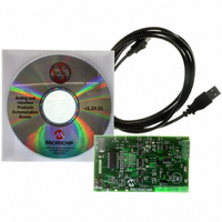
TMPSNS-RTD1
Description
BOARD EVAL PT100 RTD TEMP SENSOR
Manufacturer
Microchip Technology
Datasheets
1.MCP3301-CIMS.pdf
(32 pages)
2.PCM18XR1.pdf
(438 pages)
3.MCP6S22DM-PICTL.pdf
(43 pages)
4.TMPSNS-RTD1.pdf
(26 pages)
Specifications of TMPSNS-RTD1
Sensor Type
Temperature
Interface
USB
Embedded
Yes, MCU, 8-Bit
Utilized Ic / Part
MCP3301, MCP6S26, PIC18F2550
Processor To Be Evaluated
MCP6S26, MCP3301, MCP6024, MCP41010, PIC18F2550, TC1071, MCP6002
Data Bus Width
12 bit
Interface Type
USB
Lead Free Status / RoHS Status
Not applicable / Not applicable
Voltage - Supply
-
Sensitivity
-
Sensing Range
-
Lead Free Status / RoHS Status
Lead free / RoHS Compliant, Not applicable / Not applicable


© 2007 Microchip Technology Inc.
2.4.1.2
The PGA is used to amplify the small voltage across the RTD. The reference input pin
of the PGA is connected to the RTD negative terminal and Channel 0 and Channel 1
are connected to the positive terminals of each RTD. This allows only the voltage
across the sensor to be amplified. The PGA has a gain error of ±1% (max.) for gains
greater than 1 V/V. Refer to the datasheet (DS21685) for details.
The RTD negative terminal and the PGA output are connected to the differential
amplifier. The differential amplifier scales the PGA output. The difference amplifier gain
is shown in Equation 2-1.
EQUATION 2-1:
2.4.1.3
The GUI uses the USB port to communicate with the PIC18F2550.
FIGURE 2-6:
When start is clicked, the macro double checks hardware availability before starting
the acquisition.
All user options such as Sampling time, Stripchart buffer size, Digi. Pot Positions,
or PGA Chn/Gain setup can be changed during acquisition.
Where:
RTD SIGNAL CHAIN
THE GRAPHICAL USER INTERFACE
R
R
F
G
= 10 kΩ
= 10 kΩ Digital Potentiometer
DIFFERENCE AMPLIFIER GAIN
Hardware Status
G
Installation and Operation
=
1
+
⎛
⎝
------------------------ -
R
G
2 R
+
×
20
F
Ω
⎞
⎠
DS51607B-page 11
Related parts for TMPSNS-RTD1
Image
Part Number
Description
Manufacturer
Datasheet
Request
R

Part Number:
Description:
Manufacturer:
Microchip Technology Inc.
Datasheet:
Part Number:
Description:
Manufacturer:
Microchip Technology Inc.
Datasheet:
Part Number:
Description:
Manufacturer:
Microchip Technology Inc.
Datasheet:
Part Number:
Description:
Manufacturer:
Microchip Technology Inc.
Datasheet:
Part Number:
Description:
Manufacturer:
Microchip Technology Inc.
Datasheet:
Part Number:
Description:
Manufacturer:
Microchip Technology Inc.
Datasheet:
Part Number:
Description:
Manufacturer:
Microchip Technology Inc.
Datasheet:
Part Number:
Description:
Manufacturer:
Microchip Technology Inc.
Datasheet: