DM164128 Microchip Technology, DM164128 Datasheet - Page 21
DM164128
Manufacturer Part Number
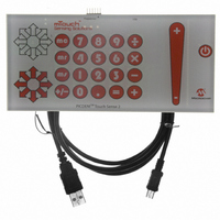
DM164128
Description
KIT DEV PICDEM TOUCH SENSE 2
Manufacturer
Microchip Technology
Series
mTouch™r
Specifications of DM164128
Sensor Type
Touch, Capacitive
Interface
Microprocessor
Embedded
Yes, MCU, 16-Bit
Utilized Ic / Part
PIC24F
Silicon Manufacturer
Microchip
Silicon Core Number
PIC24F256GB110
Features
ICSP Programming Capability, Directional Pad, Keypad And Slider Sensor
Kit Contents
Board
Lead Free Status / RoHS Status
Lead free / RoHS Compliant
Voltage - Supply
-
Sensitivity
-
Sensing Range
-
Lead Free Status / RoHS Status
Lead free / RoHS Compliant
Available stocks
Company
Part Number
Manufacturer
Quantity
Price
Company:

Part Number:
DM164128
Manufacturer:
Microchip Technology
Quantity:
135


© 2008 Microchip Technology Inc.
The upper portion of the Setup dialog allows the user to set individual values for the
Guardband and Trip Point for each sensor channel. Users may optionally set additional
reference points, labelled “Aux1” and “Aux2”. All four variables have a valid range of 0
to 65535. Each point has an additional “Visible” checkbox that determines if the value
is to be displayed on the bar graph.
The “Scale” area of the dialog is used to manually scale the bar graph. Values for the
lower limit (LL) and upper limit (UL) of the bar graph may be directly entered in the text
boxes provided; they may be set using the slider and/or bump arrow under the boxes.
As with the other set points, values for LL and UL are valid from 0 to 65,535 (provided,
of course, that UL is always greater than LL). The Autoscale R1 button automatically
selects the minimum and maximum values to be displayed for the bar graph.
FIGURE 3-5:
3.2.2.3
Within the Setup window, the Chart R1 button enables data recording from any sensor
channel. Clicking on Chart R1 opens an additional window (Figure 3-6) that displays a
plot of the channel’s conversion value versus time. Plotting of data begins immediately
when the Chart R1 is pressed, and continues to plot as long as the Run checkbox in
the Plot window is selected; pressing the Clear button erases the plot and begins a new
plot in the same window.
The range of the touch sensor values on the chart are equal to the minimum and
maximum values set for the bar graph. Data for the plot window is sampled and
displayed at a minimum rate of 10 samples per second. The amount of data displayed
(and effectively, the scale of the time axis) is changed by changing the value in the Num
Points text box. By default, the number of data points is 500.
The Log Data checkbox enables automatic logging of the channel’s data to a text file
(.txt extension). The filename is the touch sensor channel name with the .txt
extension. When the checkbox is selected, a dialog pop-up appears to confirm the file
name (generally, <channel-name>.txt) and working directory (C:\Program
Files\ Microchip\mTouch2). Data is logged to the file at the same rate as it is
plotted (5 samples per second).
Note 1:
2:
SENSOR DATA CHARTING AND LOGGING
Using the mTouch™ Sensing Solution
The Use Saved Values option button must be set for these values to
be valid and used by the demo board. See Section 3.2.2.1 “Global
Diagnostic Window Settings” for further information.
“Aux1” and “Aux2” are not available on the initial version of the mTouch
sensing solution.
SENSOR DISPLAY SETUP DIALOG BOX
DS51748A-page 17
Related parts for DM164128
Image
Part Number
Description
Manufacturer
Datasheet
Request
R

Part Number:
Description:
Manufacturer:
Microchip Technology Inc.
Datasheet:
Part Number:
Description:
Manufacturer:
Microchip Technology Inc.
Datasheet:
Part Number:
Description:
Manufacturer:
Microchip Technology Inc.
Datasheet:
Part Number:
Description:
Manufacturer:
Microchip Technology Inc.
Datasheet:
Part Number:
Description:
Manufacturer:
Microchip Technology Inc.
Datasheet:
Part Number:
Description:
Manufacturer:
Microchip Technology Inc.
Datasheet:
Part Number:
Description:
Manufacturer:
Microchip Technology Inc.
Datasheet:
Part Number:
Description:
Manufacturer:
Microchip Technology Inc.
Datasheet: