EVAL-ADXRS614Z Analog Devices Inc, EVAL-ADXRS614Z Datasheet - Page 10
EVAL-ADXRS614Z
Manufacturer Part Number
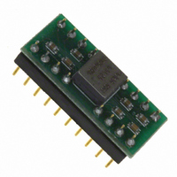
EVAL-ADXRS614Z
Description
BOARD PROTO W/ADXRS614BBGZ
Manufacturer
Analog Devices Inc
Specifications of EVAL-ADXRS614Z
Sensor Type
Gyroscope, 1 Axis
Sensing Range
±75°/sec
Interface
Analog
Sensitivity
25 mV/°/s
Voltage - Supply
4.75 V ~ 5.25 V
Embedded
No
Utilized Ic / Part
ADXRS614
Silicon Manufacturer
Analog Devices
Application Sub Type
Angular Rate Sensor / Gyroscope
Kit Application Type
Sensing - Motion / Vibration / Shock
Silicon Core Number
ADXRS614
Kit Contents
Board
Rohs Compliant
Yes
Lead Free Status / RoHS Status
Lead free / RoHS Compliant
Available stocks
Company
Part Number
Manufacturer
Quantity
Price
Company:

Part Number:
EVAL-ADXRS614Z
Manufacturer:
Analog Devices Inc
Quantity:
135


ADXRS614
behavior. Typical ratiometricity error for null, sensitivity, self-
test, and temperature output is outlined in Table 3.
Note that V
Table 3. Ratiometricity Error for Various Parameters
Parameter
ST1
ST2
Null
Sensitivity
V
NULL ADJUSTMENT
The nominal 2.5 V null is for a symmetrical swing range at
RATEOUT (1B, 2A). However, a nonsymmetrical output swing
may be suitable in some applications. Null adjustment is
possible by injecting a suitable current to SUMJ (1C, 2C). Note
that supply disturbances may reflect some null instability.
Digital supply noise should be avoided particularly in this case.
TEMP
Mean
Sigma
Mean
Sigma
Mean
Sigma
Mean
Sigma
Mean
Sigma
RATIO
V
−0.4%
0.6%
−0.4%
0.6%
−0.04%
0.3%
0.03%
0.1%
−0.3%
0.1%
must never be greater than AV
S
= V
RATIO
= 4.75 V
V
−0.3%
0.6%
−0.3%
0.6%
−0.02%
0.2%
0.1%
0.1%
−0.5%
0.1%
S
= V
CC.
RATIO
= 5.25 V
Rev. A | Page 10 of 12
SELF-TEST FUNCTION
The ADXRS614 includes a self-test feature that actuates each of
the sensing structures and associated electronics as if subjected
to angular rate. It is activated by standard logic high levels
applied to Input ST1 (5F, 5G), Input ST2 (4F, 4G), or both. ST1
causes the voltage at RATEOUT to change about −1.9 V, and
ST2 causes an opposite change of +1.9 V. The self-test response
follows the viscosity temperature dependence of the package
atmosphere, approximately 0.25%/°C.
Activating both ST1 and ST2 simultaneously is not damaging.
ST1 and ST2 are fairly closely matched (±5%), but actuating
both simultaneously may result in a small apparent null bias
shift proportional to the degree of self-test mismatch.
ST1 and ST2 are activated by applying a voltage of greater than
0.8 × V
deactivated by applying a voltage of less than 0.2 × V
ST1 pin and the ST2 pin. The voltage applied to ST1 and ST2
must never be greater than AV
CONTINUOUS SELF-TEST
The one-chip integration of the ADXRS614 gives it higher
reliability than is obtainable with any other high volume
manufacturing method. In addition, it is manufactured under a
mature BiMOS process with field-proven reliability. As an
additional failure detection measure, a power-on self-test can be
performed. However, some applications may warrant
continuous self-test while sensing rate. Details outlining
continuous self-test techniques are also available in a separate
application note.
RATIO
to the ST1 and ST2 pins. ST1 and ST2 are
CC
.
RATIO
to the
Related parts for EVAL-ADXRS614Z
Image
Part Number
Description
Manufacturer
Datasheet
Request
R


Part Number:
Description:
BOARD EVAL FOR SI270X-A
Manufacturer:
Silicon Laboratories Inc
Datasheet:

Part Number:
Description:
BUCK CONV REF DESIGN KIT IP1201
Manufacturer:
International Rectifier
Datasheet:
Part Number:
Description:
BOARD DEMO SYNC DUAL BUCK CNVTER
Manufacturer:
International Rectifier
Datasheet:
Part Number:
Description:
BOARD DEMO SYNC BUCK CONVETER
Manufacturer:
International Rectifier
Datasheet:

Part Number:
Description:
EVALBOARD/EB Omnidirectional microphone - Analog
Manufacturer:
Analog Devices
Datasheet:
Part Number:
Description:
EVALBOARD/EB Omnidirectional microphone - Analog
Manufacturer:
Analog Devices
Datasheet:


Part Number:
Description:
BOARD EVAL LED DRIVER LT3756
Manufacturer:
Linear Technology
Datasheet:

Part Number:
Description:
BOARD EVAL FOR AD7741/7742
Manufacturer:
Analog Devices Inc
Datasheet:

Part Number:
Description:
±1.7g Dual-Axis IMEMS Accelerometer Evaluation Board
Manufacturer:
Analog Devices Inc
Datasheet:

Part Number:
Description:
IC MULTIPLIER ANALOG 8-SOIC T/R
Manufacturer:
Analog Devices Inc
Datasheet:

Part Number:
Description:
IC ANALOG MULTIPLIER 8-DIP
Manufacturer:
Analog Devices Inc
Datasheet:
Part Number:
Description:
IC ANALOG MULTIPLIER 8-SOIC
Manufacturer:
Analog Devices Inc
Datasheet:
Part Number:
Description:
IC ANALOG MULTIPLIER 8-DIP
Manufacturer:
Analog Devices Inc
Datasheet: