ADIS16204/PCBZ Analog Devices Inc, ADIS16204/PCBZ Datasheet - Page 20
ADIS16204/PCBZ
Manufacturer Part Number
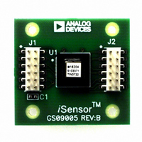
ADIS16204/PCBZ
Description
BOARD EVAL FOR ADIS16204/PCB
Manufacturer
Analog Devices Inc
Series
iMEMS®, iSensor™r
Datasheets
1.ADIS16209PCBZ.pdf
(2 pages)
2.ADIS16204PCBZ.pdf
(24 pages)
3.ADIS16204PCBZ.pdf
(2 pages)
Specifications of ADIS16204/PCBZ
Sensor Type
Accelerometer, 2 Axis
Sensing Range
±37g, ±70g
Interface
SPI Serial
Sensitivity
8.407mg/LSB, 17.125mg/LSB
Voltage - Supply
3 V ~ 3.6 V
Embedded
No
Utilized Ic / Part
ADIS16204
Silicon Manufacturer
Analog Devices
Application Sub Type
Accelerometer - Dual-Axis
Kit Application Type
Sensing - Motion / Vibration / Shock
Silicon Core Number
ADIS16204
Kit Contents
Board
Lead Free Status / RoHS Status
Lead free / RoHS Compliant
For Use With
ADISUSBZ - KIT EVAL ADIS W/SOFTWARE USBADISEVALZ - KIT PC EVALUATION W/SOFTWARE
Lead Free Status / RoHS Status
Lead free / RoHS Compliant, Lead free / RoHS Compliant
Available stocks
Company
Part Number
Manufacturer
Quantity
Price
Company:

Part Number:
ADIS16204/PCBZ
Manufacturer:
Analog Devices Inc
Quantity:
135


ADIS16204
2.
Setting Bit 11 of the MSC_CTRL register to a 1 enables the
event capture back-up function, effectively making it nonvolatile.
When enabled, this function copies the contents of the capture
buffer (right after it fills) to flash memory and restores it upon
reset or powering the device on. It continues to do so until the
buffer is cleared, using the COMMAND register. To enable this
feature, use the following pseudo code:
3. Clear the Capture Memory Locations.
Use the following pseudo code to clear both the normal capture
locations (SRAM) and their respective flash memory locations:
4. Set Up a Digital I/O Line as an Alarm Indicator.
5. Set Each Alarm as a Trigger Source for the Buffer.
These steps require configuration of the lower byte in the
ALM_CTRL register. The following pseudo code establishes
Digital I/O Line 2 as a positive signal, alarm indicator, if
necessary. It also arms both triggers for the event recorder.
If a digital alarm indicator function were not required, the
pseudo code would be:
Table 35. CAPT_CFG Register Definition
Address
0x39, 0x38
Table 36. CAPT_CFG Bit Descriptions
Bit
15:12
11:8
7:4
3:0
Configure the Capture Backup Memory.
Description
Data source for Capture Buffer 2
Data source for Capture Buffer 1
(See Capture Buffer 2 for binary coding)
Pretrigger length
Power of two setting determines length.
0111b = 7d, which corresponds to 2
this setting is greater than the data length, its value is
truncated and all captured samples are prior to the trigger
Capture buffer length
Power of two setting determine length.
1010b = 10d, which corresponds to 2
The lowest setting is a 3, which corresponds to 8 samples
Write 0x08 to Address 0x35 [MSC_CTRL].
Write 0x03 to Address 0x3F [COMMAND].
Write 0x57 to Address 0x28 [ALM_CTRL].
Write 0x50 to Address 0x28 [ALM_CTRL].
0001= power supply
0010= X-axis acceleration
0011= Y-axis acceleration
0100= auxiliary ADC
0101= temperature sensor
1000= XY RSS acceleration
Scale
N/A
Default
0x327A
Format
N/A
7
= 128 samples. If
10
= 1024 samples.
Access
R/W
Rev. B | Page 20 of 24
Event Capture Data Access
Two output registers provide the necessary access for the
ADIS16204’s capture buffers: CAPT_BUF_1 and CAPT_BUF_2.
At the completion of a capture event, the contents of theses
registers contain the first sample from each buffer. Figure 25
provides a diagram that displays the role played by the
CAPT_PNTR register in this process. This register provides a
pointer function and automatically increments every time
one of the CAP_BUF_x registers are read. If efficient data
transfer rates are a primary goal, then read all of the contents
of one buffer, before moving to the other buffer. Because the
CAPT_PNTR offers both read and write access, individual
buffer locations can be accessed by writing the sample number
into this register.
Table 37. Capture Register Definitions
Address
CAPT_BUF_1
CAPT_BUF_2
Table 38. CAPT_BUF_1 and CAPT_BUF_2 Bit Descriptions
Bit
15
14
13:0
Table 39. CAPT_PNTR Register Definition
Address
0x2B, 0x2A
Table 40. CAPT_PNTR Bit Descriptions
Bit
15:11
10:0
CAPT_BUF_1
Description
Not used
Error/alarm condition (use to identify transition between
pre-trigger and post-trigger data)
Data bits. Format matches that of the data source
Description
Not used
Capture address pointer: A binary number from 1 to
1024, which identifies the address of each individual
capture buffer sample.
Figure 25. Event Capture Buffer Memory Structure
USER ACCESIBLE
INTERNAL MEMORY STRUCUTRE
Address
0x1D, 0x1C
0x1E, 0x1F
Scale
N/A
BUFFER 1
Default
N/A
Format
The format and scale
match that of the
output data being
monitored
CAPT_BUF_2
CAPT_PNTR
Format
Binary
BUFFER 2
Access
R/W
Access
R only
Related parts for ADIS16204/PCBZ
Image
Part Number
Description
Manufacturer
Datasheet
Request
R

Part Number:
Description:
±1.7g Dual-Axis IMEMS Accelerometer Evaluation Board
Manufacturer:
Analog Devices Inc
Datasheet:

Part Number:
Description:
Inertial Sensor Evaluation System
Manufacturer:
Analog Devices Inc
Datasheet:
Part Number:
Description:
Manufacturer:
Analog Devices Inc
Datasheet:
Part Number:
Description:
Manufacturer:
Analog Devices Inc
Datasheet:
Part Number:
Description:
Manufacturer:
Analog Devices Inc
Datasheet:
Part Number:
Description:
Manufacturer:
Analog Devices Inc
Datasheet:
Part Number:
Description:
Manufacturer:
Analog Devices Inc
Datasheet:
Part Number:
Description:
Manufacturer:
Analog Devices Inc
Datasheet:
Part Number:
Description:
Manufacturer:
Analog Devices Inc
Datasheet:
Part Number:
Description:
Manufacturer:
Analog Devices Inc
Datasheet:
Part Number:
Description:
Manufacturer:
Analog Devices Inc
Datasheet:
Part Number:
Description:
Manufacturer:
Analog Devices Inc
Datasheet:
Part Number:
Description:
Manufacturer:
Analog Devices Inc
Datasheet: