ADIS16201/PCBZ Analog Devices Inc, ADIS16201/PCBZ Datasheet - Page 27
ADIS16201/PCBZ
Manufacturer Part Number
ADIS16201/PCBZ
Description
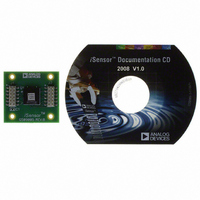
BOARD EVAL PCB ADIS16201
Manufacturer
Analog Devices Inc
Series
iMEMS®, iSensor™r
Specifications of ADIS16201/PCBZ
Sensor Type
Accelerometer, Inclinometer, 2 Axis
Sensing Range
±1.7g, ±90°
Interface
SPI Serial
Sensitivity
2 LSB/mg, 10 LSB/°
Voltage - Supply
3 V ~ 3.6 V
Embedded
No
Utilized Ic / Part
ADIS16201
Silicon Manufacturer
Analog Devices
Application Sub Type
Accelerometer - Dual-Axis
Kit Application Type
Sensing - Motion / Vibration / Shock
Silicon Core Number
ADIS16201
Kit Contents
Board
Lead Free Status / RoHS Status
Lead free / RoHS Compliant
For Use With
ADISUSBZ - KIT EVAL ADIS W/SOFTWARE USBADISEVALZ - KIT PC EVALUATION W/SOFTWARE
Lead Free Status / RoHS Status
Lead free / RoHS Compliant, Lead free / RoHS Compliant
Other names
ADIS16201/PCB
ADIS16201/PCB
ADIS16201/PCB


PERIPHERALS
AUXILIARY ADC FUNCTION
The auxiliary ADC function integrates a standard 12-bit ADC
into the ADIS16201 to digitize other system-level analog signals.
The output of the ADC can be monitored through the AUX_ADC
control register, as defined in Table 6 and Table 7. The ADC
consists of a 12-bit successive approximation converter. The
output data is presented in straight binary format, with the full
scale range extending from 0 V to VREF. A high precision, low
drift, factory-calibrated 2.5 V reference is also provided.
Figure 38 shows the equivalent circuit of the analog input
structure of the ADC. The input capacitor, C1, is typically 4 pF
and can be attributed to parasitic package capacitance. The two
diodes provide ESD protection for the analog input. Care must
be taken to ensure that the analog input signals never exceed
the supply rails by more than 300 mV. This would cause these
diodes to become forward-biased and start conducting. They
can handle 10 mA without causing irreversible damage to the
part. The resistor is a lumped component that represents the on
resistance of the switches. The value of this resistance is typically
100 Ω. Capacitor C2 represents the ADC sampling capacitor
and is typically 16 pF.
For ac applications, removing high frequency components from
the analog input signal is recommended through the use of an
RC low-pass filter on the relevant analog input pins.
In applications where harmonic distortion and signal-to-noise
ratio are critical, the analog input should be driven from a low
impedance source. Large source impedances significantly affect
the ac performance of the ADC. This can necessitate the use of
an input buffer amplifier. When no input amplifier is used to
drive the analog input, the source impedance should be limited
to values lower than 1 kΩ. The maximum source impedance
depends on the amount of total harmonic distortion (THD)
that can be tolerated.
Figure 38. Equivalent Analog Input Circuit
Conversion Phase: Switch Open
C1
Track Phase: Switch Closed
VDD
D
D
R1
C2
Rev. A | Page 27 of 32
AUXILIARY DAC FUNCTION
The auxiliary DAC function integrates a standard 12-bit DAC
into the ADIS16201. The DAC output is buffered and fed off-
chip to allow for the control of miscellaneous system-level
functions. Data is downloaded through the writing of two
adjacent data bytes, as defined in its register definition. To
prevent the DAC from transitioning through inadvertent states
during data downloads, a single command is used to
simultaneously latch both data bytes into the DAC after they
have been written into the AUX_DAC control register. This
command is implemented by writing 1 to Bit 2 of the command
control register, which, once received, results in the DAC output
transitioning to the desired state.
The DAC output provides an output range of 0 V to 2.5 V. The
DAC output buffer features a true rail-to-rail output stage. This
means that, unloaded, the output is capable of reaching within
5 mV of ground. Moreover, the DAC’s linearity performance
(when driving a 5 kΩ resistive load to ground) is good through
the full transfer function, except for Code 0 to Code 100.
Linearity degradation near ground is caused by saturation of the
output amplifier. As the output is forced to sink more current,
the nonlinear region at the bottom of the transfer function
becomes larger. Larger current demands can significantly limit
output voltage swing.
AUX_DAC Register Definition
Address
0x31, 0x30
1
The AUX_DAC register controls the ADIS16201’s DAC function.
The data bits provide a 12-bit binary format number with 0
representing 0 V and 0x0FFFh representing 2.5 V. The data
within this register is volatile and is set to 0s upon reset. This
register has read/write capability.
Table 30. AUX_DAC Bit Descriptions
Bit
15:12
11:0
Default is valid only until the first register write cycle.
Default
0x0000
Description
Not used
Data bits
1
Format
Binary
ADIS16201
Access
R/W
Related parts for ADIS16201/PCBZ
Image
Part Number
Description
Manufacturer
Datasheet
Request
R

Part Number:
Description:
BOARD EVAL ADIS16201 W/SOFTWARE
Manufacturer:
Analog Devices Inc
Datasheet:

Part Number:
Description:
±1.7g Dual-Axis IMEMS Accelerometer Evaluation Board
Manufacturer:
Analog Devices Inc
Datasheet:
Part Number:
Description:
Inertial Sensor Evaluation System
Manufacturer:
Analog Devices Inc
Datasheet:
Part Number:
Description:
Manufacturer:
Analog Devices Inc
Datasheet:
Part Number:
Description:
Manufacturer:
Analog Devices Inc
Datasheet:
Part Number:
Description:
Manufacturer:
Analog Devices Inc
Datasheet:
Part Number:
Description:
Manufacturer:
Analog Devices Inc
Datasheet:
Part Number:
Description:
Manufacturer:
Analog Devices Inc
Datasheet:
Part Number:
Description:
Manufacturer:
Analog Devices Inc
Datasheet:
Part Number:
Description:
Manufacturer:
Analog Devices Inc
Datasheet:
Part Number:
Description:
Manufacturer:
Analog Devices Inc
Datasheet:
Part Number:
Description:
Manufacturer:
Analog Devices Inc
Datasheet:
Part Number:
Description:
Manufacturer:
Analog Devices Inc
Datasheet: