EVB90614 Melexis Inc, EVB90614 Datasheet - Page 10
EVB90614
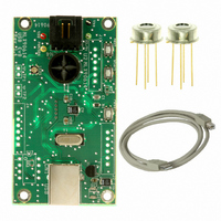
Manufacturer Part Number
EVB90614
Description
BOARD EVAL FOR MLX90614
Manufacturer
Melexis Inc
Specifications of EVB90614
Sensor Type
Temperature
Sensing Range
-40°C ~ 125°C
Interface
SMBus (2-Wire/I²C)
Embedded
Yes, MCU, 8-Bit
Utilized Ic / Part
MLX90614
Lead Free Status / RoHS Status
Lead free / RoHS Compliant
Voltage - Supply
-
Sensitivity
-


8 Detailed description
8.1 Block diagram
8.2 Signal processing principle
The operation of the MLX90614 is controlled by an internal state machine, which controls the measurements
and calculations of the object and ambient temperatures and does the post-processing of the temperatures to
output them through the PWM output or the SMBus compatible interface.
The ASSP supports 2 IR sensors (second one not implemented in the MLX90614xAx).The output of the IR
sensors is amplified by a low noise low offset chopper amplifier with programmable gain, converted by a
Sigma Delta modulator to a single bit stream and fed to a powerful DSP for further processing. The signal is
treated by programmable (by means of EEPROM contend) FIR and IIR low pass filters for further reduction of
the band width of the input signal to achieve the desired noise performance and refresh rate. The output of
the IIR filter is the measurement result and is available in the internal RAM. 3 different cells are available:
One for the on-board temperature sensor (on chip PTAT or PTC) and 2 for the IR sensors.
Based on results of the above measurements, the corresponding ambient temperature Ta and object
temperatures To are calculated. Both calculated temperatures have a resolution of 0.01 ˚C. The data for Ta
and To can be read in two ways: Reading RAM cells dedicated for this purpose via the 2-wire interface
(0.02° C resolution, fixed ranges), or through the PWM digital output (10 bit resolution, configurable range).
In the last step of the measurement cycle, the measured Ta and To are rescaled to the desired output
resolution of the PWM) and the recalculated data is loaded in the registers of the PWM state machine, which
creates a constant frequency with a duty cycle representing the measured data.
3901090614
Rev 006
81101
90302
t°
Figure 3: Block diagram
OPA
Page 10 of 49
STATE MACHINE
ADC
Infra Red Thermometer in TO-39
DSP
Voltage
Regulator
Single and Dual Zone
PWM
September 30, 2010
Data Sheet
Related parts for EVB90614
Image
Part Number
Description
Manufacturer
Datasheet
Request
R

Part Number:
Description:
BOARD EVALUATION FOR EMC1043
Manufacturer:
SMSC
Datasheet:

Part Number:
Description:
IC LATCH CMOS MP TSOT23-3
Manufacturer:
Melexis Inc
Datasheet:

Part Number:
Description:
IC LATCH CMOS MP TSOT23-3
Manufacturer:
Melexis Inc
Datasheet:

Part Number:
Description:
IC HALL EFFECT SW TSOT-23
Manufacturer:
Melexis Inc
Datasheet:

Part Number:
Description:
IC HALL EFFECT SWITCH TSOT-23
Manufacturer:
Melexis Inc
Datasheet:

Part Number:
Description:
IC HALL EFFECT SW
Manufacturer:
Melexis Inc
Datasheet:

Part Number:
Description:
IC HALL EFFECT SWITCH TSOT-23
Manufacturer:
Melexis Inc
Datasheet:

Part Number:
Description:
IC HALL EFFECT SWITCH TSOT-23
Manufacturer:
Melexis Inc
Datasheet: