EVAL-ADXL345Z-M Analog Devices Inc, EVAL-ADXL345Z-M Datasheet - Page 31
EVAL-ADXL345Z-M
Manufacturer Part Number
EVAL-ADXL345Z-M
Description
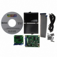
BOARD EVAL FOR ADXL345
Manufacturer
Analog Devices Inc
Series
iMEMS®r
Datasheets
1.EVAL-ADXL345Z.pdf
(40 pages)
2.EVAL-ADXL345Z.pdf
(2 pages)
3.EVAL-ADXL345Z.pdf
(12 pages)
4.EVAL-ADXL345Z-S.pdf
(2 pages)
Specifications of EVAL-ADXL345Z-M
Sensor Type
Accelerometer, 3 Axis
Sensing Range
±2g, 4g, 8g, 16g
Interface
I²C, SPI
Sensitivity
256 LSB/g
Voltage - Supply
1.8 V ~ 3.6 V
Embedded
No
Utilized Ic / Part
ADXL345
Silicon Manufacturer
Analog Devices
Application Sub Type
Accelerometer - Three-Axis
Kit Application Type
Sensing - Motion / Vibration / Shock
Silicon Core Number
ADXL345
Lead Free Status / RoHS Status
Lead free / RoHS Compliant
Available stocks
Company
Part Number
Manufacturer
Quantity
Price
Company:

Part Number:
EVAL-ADXL345Z-M
Manufacturer:
Analog Devices Inc
Quantity:
135


USING SELF-TEST
The self-test change is defined as the difference between the
acceleration output of an axis with self-test enabled and the
acceleration output of the same axis with self-test disabled (see
Endnote 4 of Table 1). This definition assumes that the sensor
does not move between these two measurements, because if the
sensor moves, a non–self-test related shift corrupts the test.
Proper configuration of the ADXL345 is also necessary for an
accurate self-test measurement. The part should be set with a
data rate greater than or equal to 100 Hz. This is done by
ensuring that a value greater than or equal to 0x0A is written
into the rate bits (Bit D3 through Bit D0) in the BW_RATE
register (Address 0x2C). The part also must be placed into
normal power operation by ensuring the LOW_POWER bit in
the BW_RATE register is cleared (LOW_POWER bit = 0) for
accurate self-test measurements. It is recommended that the
part be set to full-resolution, 16 g mode to ensure that there is
sufficient dynamic range for the entire self-test shift. This is done
by setting Bit D3 of the DATA_FORMAT register (Address 0x31)
and writing a value of 0x03 to the range bits (Bit D1 and Bit D0) of
the DATA_FORMAT register (Address 0x31). This results in a high
dynamic range for measurement and a 3.9 mg/LSB scale factor.
After the part is configured for accurate self-test measurement,
several samples of x-, y-, and z-axis acceleration data should be
retrieved from the sensor and averaged together. The number
of samples averaged is a choice of the system designer, but a
recommended starting point is 0.1 sec worth of data for data
rates of 100 Hz or greater. This corresponds to 10 samples at
the 100 Hz data rate. For data rates less than 100 Hz, it is
recommended that at least 10 samples be averaged together. The
averaged values should be stored and labeled appropriately as
the self-test disabled data, that is, X
ST_OFF
, Y
ST_OFF
, and Z
ST_OFF
.
Rev. B | Page 31 of 40
Next, self-test should be enabled by setting Bit D7 (SELF_TEST) of
the DATA_FORMAT register (Address 0x31). The output needs
some time (about four samples) to settle after enabling self-test.
After allowing the output to settle, several samples of the x-, y-,
and z-axis acceleration data should be taken again and averaged. It
is recommended that the same number of samples be taken for
this average as was previously taken. These averaged values should
again be stored and labeled appropriately as the value with self-
test enabled, that is, X
disabled by clearing Bit D7 (SELF_TEST) of the DATA_FORMAT
register (Address 0x31).
With the stored values for self-test enabled and disabled, the
self-test change is as follows:
Because the measured output for each axis is expressed in LSBs,
X
converted to g’s of acceleration by multiplying each value by the
3.9 mg/LSB scale factor, if configured for full-resolution mode.
Additionally, Table 15 through Table 18 correspond to the self-test
range converted to LSBs and can be compared with the measured
self-test change when operating at a V
the minimum and maximum self-test output values should be
adjusted based on (multiplied by) the scale factors shown in
Table 14. If the part was placed into ±2 g, 10-bit or full-resolution
mode, the values listed in Table 15 should be used. Although
the fixed 10-bit mode or a range other than 16 g can be used, a
different set of values, as indicated in Table 16 through Table 18,
would need to be used. Using a range below 8 g may result in
insufficient dynamic range and should be considered when
selecting the range of operation for measuring self-test.
If the self-test change is within the valid range, the test is considered
successful. Generally, a part is considered to pass if the minimum
magnitude of change is achieved. However, a part that changes
by more than the maximum magnitude is not necessarily a failure.
ST
, Y
X
Y
Z
ST
ST
ST
ST
, and Z
= Y
= Z
= X
ST_ON
ST_ON
ST_ON
ST
− Z
are also expressed in LSBs. These values can be
− Y
− X
ST_OFF
ST_OFF
ST_ON
ST_OFF
, Y
ST_ON
, and Z
S
of 2.5 V. For other voltages,
ST_ON
. Self-test can then be
ADXL345
Related parts for EVAL-ADXL345Z-M
Image
Part Number
Description
Manufacturer
Datasheet
Request
R


Part Number:
Description:
BOARD EVAL FOR SI270X-A
Manufacturer:
Silicon Laboratories Inc
Datasheet:

Part Number:
Description:
BUCK CONV REF DESIGN KIT IP1201
Manufacturer:
International Rectifier
Datasheet:
Part Number:
Description:
BOARD DEMO SYNC DUAL BUCK CNVTER
Manufacturer:
International Rectifier
Datasheet:
Part Number:
Description:
BOARD DEMO SYNC BUCK CONVETER
Manufacturer:
International Rectifier
Datasheet:

Part Number:
Description:
EVALBOARD/EB Omnidirectional microphone - Analog
Manufacturer:
Analog Devices
Datasheet:
Part Number:
Description:
EVALBOARD/EB Omnidirectional microphone - Analog
Manufacturer:
Analog Devices
Datasheet:


Part Number:
Description:
BOARD EVAL LED DRIVER LT3756
Manufacturer:
Linear Technology
Datasheet:

Part Number:
Description:
BOARD EVAL FOR AD7741/7742
Manufacturer:
Analog Devices Inc
Datasheet:

Part Number:
Description:
±1.7g Dual-Axis IMEMS Accelerometer Evaluation Board
Manufacturer:
Analog Devices Inc
Datasheet:

Part Number:
Description:
IC MULTIPLIER ANALOG 8-SOIC T/R
Manufacturer:
Analog Devices Inc
Datasheet:

Part Number:
Description:
IC ANALOG MULTIPLIER 8-DIP
Manufacturer:
Analog Devices Inc
Datasheet:
Part Number:
Description:
IC ANALOG MULTIPLIER 8-SOIC
Manufacturer:
Analog Devices Inc
Datasheet:
Part Number:
Description:
IC ANALOG MULTIPLIER 8-DIP
Manufacturer:
Analog Devices Inc
Datasheet: