ADIS16223/PCBZ Analog Devices Inc, ADIS16223/PCBZ Datasheet
ADIS16223/PCBZ
Specifications of ADIS16223/PCBZ


Related parts for ADIS16223/PCBZ


ADIS16223/PCBZ Summary of contents
Page 1
Getting Started with the ADIS1622x Evaluation Tools The World Leader in High Performance Signal Processing Solutions ® iSensor Mark Looney iSensor Applications Engineer December 2010 ...
Page 2
... Table of Contents, ADIS1622x Evaluation Tools TITLE/TOPIC Hardware: ADIS1622x/PCBZ, ADISUSBZ ADIS16220/PCBZ Documentation ADIS16220/PCBZ Physical Installation on an ADISUSBZ ADIS16223/PCBZ, ADIS16227/PCBZ: Schematic & Mounting Hole Pattern ADIS16223/PCBZ, ADIS16227/PCBZ: Physical Installation on an ADISUSBZ ADIS16223/PCBZ, ADIS16227/PCBZ: Ribbon Mating Cable Design Remote Mounting Option ADIS16220 Evaluation Software Installation ...
Page 3
... Eliminates the need to solder the LGA package in a prototype process. 2. Connects directly to the PC-USB evaluation system, ADISUSBZ 3. ADIS16223/PCBZ, ADIS16227/PCBZ Interface boards Provides ADIS16223CMLZ on a small PCB with a 2mm connector. 1. Eliminates the need to develop a prototype board with the mating connector. 2. Connects directly to the PC-USB evaluation system, ADISUSBZ 3 ...
Page 4
The Simple Solution for Sensor Integration ADIS16220/PCBZ J1/J2 PIN NUMBERS ADIS16220CCCZ RST SCLK DOUT ...
Page 5
The Simple Solution for Sensor Integration ADIS16220/PCBZ Installation on ADISUSBZ Installation Steps 1. Remove ribbon cable & (2) 2mm screws. 2. Place ADIS16220/PCBZ on the ADISUSBZ, using the silk screen and four corner mounting holes as a guide. ...
Page 6
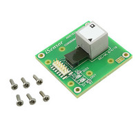
... The Simple Solution for Sensor Integration ADIS16223/PCBZ, ADIS16227/PCBZ A. ADIS16223CMLZ bolted to the interface board using: Fastener Express p/n FHS1106-4I2 , flat head 10/32x3/8”. B. Interface board general-purpose mounting holes. Use M2 (2mm) machine screws to help manage potential PCB-level resonance threats. C. ADISUSBZ mounting holes. ...
Page 7
... The Simple Solution for Sensor Integration ADIS16223/PCBZ, ADIS16227/PCBZ; ADISUSBZ Installation 1. Bend ribbon cable back. 2. Remove M2 screws if they are present. 3. Place M2x6mm screws in six ADISUSB mounting holes. 4. Place ADIS1622x/PCBZ onto the ADISUSBZ and tighten screws. 5. Connect ribbon cable, making sure that it is aligned with upper 12 pins. 6. Set JP1 to “ ...
Page 8
The Simple Solution for Sensor Integration ADIS1622x/PCBZ Ribbon Cable Interface J1/J2 Ribbon Cable Interface Parts Ribbon Crimp Connector 3M P/N 152212-0100-GB Ribbon Cable 3M P/N 3625/12 (100m) 8 ADISUSBZ uses the following cable assembly from Samtec: ASP-140062-01 ...
Page 9
The Simple Solution for Sensor Integration Alternate Use for Best Mechanical Coupling 1. Remove ADIS1622xCMLZ from ADIS1622x/PCBZ by carefully unplugging the flex (it can break) and the 10-32 screw on the bottom side. 2. Cut the interface board ...
Page 10
The Simple Solution for Sensor Integration ADIS1622x Evaluation Software Installation 10 The ADIS16220, ADIS16223, and ADIS16227 have their own demo/evaluation software packages, which can be downloaded from each product’s web page at www.analog.com. Use the following steps to ...
Page 11
The Simple Solution for Sensor Integration ADIS1622x Evaluation Software Installation Installation Steps (continued) 4. Unpack contents from zipped file and click on “setup.exe”. 5. Click OK on the next screen. 6. Click on computer icon to start the ...
Page 12
The Simple Solution for Sensor Integration ADIS1622x Evaluation Software Installation Installation Steps (continued) 7. Click Continue window like this appears, we suggest keeping the existing files. In this case, click "Yes" to keep existing files. ...
Page 13
The Simple Solution for Sensor Integration ADIS1622x Evaluation Software Installation Installation Steps (continued) 9. Open the newly created directory and double-click onto “giveio.exe”. 10. Click “Install”. 13 ...
Page 14
The Simple Solution for Sensor Integration ADIS1622x Evaluation Software Installation Installation Steps (continued) 11. Click “Install”. 12. Click “Yes”. 13. Giveio Driver complete. Click “Ok”. 14 ...
Page 15
The Simple Solution for Sensor Integration MCP USB Driver Installation Installation Steps 1. Plug the ADISUSBZ to the PC using an A-to-B USB cable. The USB Driver screen will pop-up. Click “Next” to start this process. 2. Then ...
Page 16
The Simple Solution for Sensor Integration ADIS1622x Software Tips, Manual Trigger Mode 16 1. Click on “Interface” and select USB, then OK when the pop-up window shows the USB device is connected. 2. Software should start up and ...
Page 17
... Since the ADISUSBZ doesn’t connect to the “Busy” signal, DIO1 per factory default, use the LEDs on the ADIS16223/PCBZ to determine if the device is busy. Do not attempt to read when the LED is on. Note that the ADISUSBZ takes a few seconds to read and process the data ...
Page 18
The Simple Solution for Sensor Integration ADIS1622x Software Tips, Event Trigger Mode 18 1. Use the pull-down menu to set the device up for “Event Capture Mode”. ...
Page 19
The Simple Solution for Sensor Integration ADIS1622x Software Tips, Event Trigger Mode 19 2. Use the “ALARMS” option in the configuration pull-down menu to set up the trigger levels. ...
Page 20
The Simple Solution for Sensor Integration ADIS1622x Software Tips, Event Trigger Mode, Alarms this example, enable each alarm, then enter the acceleration threshold for triggering the capture this case, enter “10”, then click ...
Page 21
The Simple Solution for Sensor Integration ADIS1622x Software Tips, Event Mode Capture Example 21 1. Click on “Arm” and notice that the DIO1 LED light turns on. 2. Tap the assembly on non-valuable surface. Increase the intensity of ...
Page 22
The Simple Solution for Sensor Integration ADIS1622x Software Tips, Filtering, No Filtering Enabled 22 1. The ADIS1622x are wide- band filters. 2. Lower frequency applications tend to value lower noise. 3. The filtering helps optimize the noise and ...
Page 23
The Simple Solution for Sensor Integration ADIS1622x Software Tips, Band-Pass Filtering 23 1. Enable the band-pass filter. 2. Click on Trigger. 3. Notices the lower amount of noise and the fact that it is centered around 0g now. ...
Page 24
The Simple Solution for Sensor Integration ADIS1622x Software Tips, Band-Pass & Low-Pass Filtering 24 1. Click on the AVG_CNT pull-down menu and select 64. 2. Click on Trigger. 3. Observe the lower noise and longer capture time. ...
Page 25
The Simple Solution for Sensor Integration ADIS16227 Software Tips: Basic Setup 25 1. Double click on the ADIS16227*.exe file to start the software. 2. Make sure that the settings under “Main Control” and “Sample Rate Options” match those ...
Page 26
The Simple Solution for Sensor Integration ADIS16227 Software Tips: Basic Demo 26 1. Shake the ADIS16227 in a repetitive manner and click on “Start.” Continue the shaking until the software completes collecting data. 2. After data collection is ...
Page 27
The Simple Solution for Sensor Integration ADIS16227 Software Tips: Spectral Alarm Demo 27 1. Use the “Configuration” drop-down menu to click on the “Alarm Spectrum” option. ...
Page 28
The Simple Solution for Sensor Integration ADIS16227 Software Tips: Spectral Alarm Demo 28 2. Under “Sample Rate Option,” use the drop- down menu to select “3”. 3. Change each entry by highlighting the numbers and then typing it ...
Page 29
The Simple Solution for Sensor Integration ADIS16227 Software Tips: Spectral Alarm Demo 29 4. Enter all of the numbers show for this demo in the graphic. 5. Click on “Write All” to save them to the flash memory ...
Page 30
The Simple Solution for Sensor Integration ADIS16227 Software Tips: Spectral Alarm Demo 30 8. After returning to the main window, use the “Configuration” drop- down menu to select the “ALM_CTRL” option. 9. Use the ALM_CTRL menu to enable ...
Page 31
The Simple Solution for Sensor Integration ADIS16227 Software Tips: Spectral Alarm Demo 31 11. Repeat the shaking motion and click on “Start”. 12. Observe the Peak Alarms and Spectral Alarms outputs. ...
Page 32
Contacts: Applications Engineer: Marketing: More Information on iSensor Evaluation Tools: www.analog.com/isensor-evaluation 32 Mark Looney mark.looney@analog.com 1-336-605-4139 Bob Scannell bob.scannell@analog.com 1-336-605-4031 ...