101-1288 Rabbit Semiconductor, 101-1288 Datasheet - Page 3
101-1288
Manufacturer Part Number
101-1288
Description
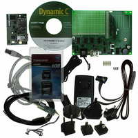
KIT APPLICATION SIMPLE SENSOR
Manufacturer
Rabbit Semiconductor
Series
RabbitCore 4000r
Specifications of 101-1288
Mfg Application Notes
Simple Sensor App Kit, AppNote
Sensor Type
Temperature
Interface
1-Wire Serial
Voltage - Supply
12V
Embedded
Yes, Other
Utilized Ic / Part
RCM4300
Maximum Operating Temperature
+ 85 C
Minimum Operating Temperature
- 20 C
Lead Free Status / RoHS Status
Lead free / RoHS Compliant
Sensitivity
-
Sensing Range
-
Lead Free Status / Rohs Status
Lead free / RoHS Compliant
Other names
316-1178


3-pin
power connector
Figure 3. Connect Programming Cable and Power Supply
Your PC should recognize the new USB hardware, and the LEDs in the shrink-wrapped area of the USB
programming cable will flash — if you get an error message, you will have to install USB drivers. Drivers
for Windows XP are available in the Dynamic C Drivers\Rabbit USB Programming Cable\
WinXP_2K folder — double-click DPInst.exe to install the USB drivers. Drivers for other operating
systems are available online at www.ftdichip.com/Drivers/VCP.htm.
Step 4 — Connect Power
Once all the other connections have been made, you can connect power to the Prototyping Board.
First, prepare the AC adapter for the country where it will be used by selecting the plug. The RCM4300
Development Kit presently includes Canada/Japan/U.S., Australia/N.Z., U.K., and European style plugs.
Snap in the top of the plug assembly into the slot at the top of the AC adapter as shown in Figure 3, then
press down on the spring-loaded clip below the plug assembly to allow the plug assembly to click into
place. Release the clip to secure the plug assembly in the AC adapter.
Connect the AC adapter to 3-pin header P1 on the Prototyping Board as shown in Figure 3. The connector
may be attached either way as long as it is not offset to one side—the center pin of P1 is always connected
to the positive terminal, and either edge pin is ground.
Plug in the AC adapter. The POWER LED on the Prototyping Board next to the power connector at P1
should light up. The RCM4300 and the Prototyping Board are now ready to be used.
NOTE: A RESET button is provided on the Prototyping Board to allow a hardware reset without
disconnecting power.
Related parts for 101-1288
Image
Part Number
Description
Manufacturer
Datasheet
Request
R

Part Number:
Description:
COMPUTER SNGLBD BL2120 FRCTNLOCK
Manufacturer:
Rabbit Semiconductor
Datasheet:

Part Number:
Description:
KIT APPLCTN RABBITCORE RCM4010
Manufacturer:
Rabbit Semiconductor
Datasheet:

Part Number:
Description:
KIT MESH NETWORK ADD-ON RCM4510W
Manufacturer:
Rabbit Semiconductor
Datasheet:

Part Number:
Description:
KIT DEV FOR BL2500 COYOTE
Manufacturer:
Rabbit Semiconductor
Datasheet:

Part Number:
Description:
KIT CAMERA INTERFACE APPLICATION
Manufacturer:
Rabbit Semiconductor
Datasheet:


Part Number:
Description:
KIT APPLICATION LCD COLOR INT'L
Manufacturer:
Rabbit Semiconductor

Part Number:
Description:
IC CPU RABBIT2000 30MHZ 100PQFP
Manufacturer:
Rabbit Semiconductor
Datasheet:

Part Number:
Description:
IC CPU RABBIT4000 128-LQFP
Manufacturer:
Rabbit Semiconductor
Datasheet:
Part Number:
Description:
IC MPU RABIT3000A 55.5MHZ128LQFP
Manufacturer:
Rabbit Semiconductor
Datasheet:

Part Number:
Description:
MODULE RABBITCORE RCM4010
Manufacturer:
Rabbit Semiconductor
Datasheet:

Part Number:
Description:
RCM4110 RABBITCORE
Manufacturer:
Rabbit Semiconductor
Datasheet:

Part Number:
Description:
MODULE RABBITCORE RCM2000
Manufacturer:
Rabbit Semiconductor
Datasheet:

Part Number:
Description:
MODULE RABBITCORE RCM3000
Manufacturer:
Rabbit Semiconductor
Datasheet:

Part Number:
Description:
MCU RCM4000 RABBITCORE
Manufacturer:
Rabbit Semiconductor
Datasheet: