STEVAL-MKI024V1 STMicroelectronics, STEVAL-MKI024V1 Datasheet
STEVAL-MKI024V1
Specifications of STEVAL-MKI024V1
Available stocks


Related parts for STEVAL-MKI024V1


STEVAL-MKI024V1 Summary of contents
Page 1
... Introduction The STEVAL-MKI024V1 is a demonstration kit designed to provide the user with a complete, ready-to-use platform for demonstration of the LIS331DL. The LIS331DL is a low- power 3-axis linear accelerometer with digital output. The device includes a sensing element and an IC interface capable of translating information from the sensing element into a measured signal that can be used for external applications ...
Page 2
... Contents Contents 1 Demonstration kit description . . . . . . . . . . . . . . . . . . . . . . . . . . . . . . . . . 5 2 STEVAL-MKI024V1 GUI installation . . . . . . . . . . . . . . . . . . . . . . . . . . . . . 7 2.1 PC system requirements . . . . . . . . . . . . . . . . . . . . . . . . . . . . . . . . . . . . . . 7 2.2 Software installation . . . . . . . . . . . . . . . . . . . . . . . . . . . . . . . . . . . . . . . . . . 7 2.3 Hardware installation . . . . . . . . . . . . . . . . . . . . . . . . . . . . . . . . . . . . . . . . . 8 3 Graphical user interface . . . . . . . . . . . . . . . . . . . . . . . . . . . . . . . . . . . . . 11 3.1 Connecting to the virtual COM port . . . . . . . . . . . . . . . . . . . . . . . . . . . . . 12 3.2 “Easy Start” button . . . . . . . . . . . . . . . . . . . . . . . . . . . . . . . . . . . . . . . . . . 12 3.3 “Options” tab . . . . . . . . . . . . . . . . . . . . . . . . . . . . . . . . . . . . . . . . . . . . . . . 13 3.4 “Register Setup” tab . . . . . . . . . . . . . . . . . . . . . . . . . . . . . . . . . . . . . . . . . 13 3.5 “ ...
Page 3
UM0692 7.2.1 7.2.2 7.2.3 7.2.4 7.2.5 7.2.6 7.2.7 7.2.8 7.2.9 7.3 Quick start . . . . . . . . . . . . . . . . . . . . . . . . . . . ...
Page 4
... List of figures List of figures Figure 1. Demonstration board block diagram . . . . . . . . . . . . . . . . . . . . . . . . . . . . . . . . . . . . . . . . . . . 5 Figure 2. Top silk screen of the STEVAL-MKI024V1 kit . . . . . . . . . . . . . . . . . . . . . . . . . . . . . . . . . . . 6 Figure 3. Board photograph . . . . . . . . . . . . . . . . . . . . . . . . . . . . . . . . . . . . . . . . . . . . . . . . . . . . . . . . . 6 Figure 4. Software installation . . . . . . . . . . . . . . . . . . . . . . . . . . . . . . . . . . . . . . . . . . . . . . . . . . . . . . . 7 Figure 5. Notify icon . . . . . . . . . . . . . . . . . . . . . . . . . . . . . . . . . . . . . . . . . . . . . . . . . . . . . . . . . . . . . . . 8 Figure 6. Driver installation using the device manager . . . . . . . . . . . . . . . . . . . . . . . . . . . . . . . . . . . . 8 Figure 7. USB driver installation using the hardware update wizard . . . . . . . . . . . . . . . . . . . . . . . . . . 9 Figure 8 ...
Page 5
... UM0692 1 Demonstration kit description The STEVAL-MKI024V1 is a complete demonstration kit that allows demonstration of the performance of the LIS331DL low-power 3-axis linear accelerometer with digital output. The block diagram of the demonstration kit is shown in Figure 1. Demonstration board block diagram MEM S senso r The ST7-USB microcontroller included on the board allows communication between the sensor device and the PC ...
Page 6
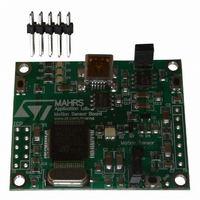
... Top silk screen of the STEVAL-MKI024V1 kit Figure 3. Board photograph Operation of the STEVAL-MKI024V1 demonstration kit requires the installation of a dedicated driver which is included in the installation pack, together with a GUI interface which allows simple interaction with the sensor. The steps required for driver and software installation are described in the following section ...
Page 7
... UM0692 2 STEVAL-MKI024V1 GUI installation The installation of the graphical user interface (GUI) for the STEVAL-MKI024V1 requires two steps: 1. installation of the software downloaded from 2. installation of the virtual COM driver needed to use the demonstration kit 2.1 PC system requirements Both the hardware and software that compose the STEVAL-MKI024V1 demonstration kit have been designed to operate with Microsoft 2 ...
Page 8
... STEVAL-MKI024V1 GUI installation 2.3 Hardware installation To install the virtual COM driver, insert the demonstration kit board into a free USB port. The “Notify” icon should appear as in Figure 5. Notify icon If the “Hardware Update Wizard” window appears screen, otherwise, the installation can be performed by following the instructions indicated in ...
Page 9
... USB driver installation using the hardware update wizard Once the installation is complete, a COM port number is assigned to the ST virtual COM driver (Figure 8). This number should be retained required to run the STEVAL- MKI024V1 demonstration software GUI. For additional details, see STEVAL-MKI024V1 GUI installation AM01771v1 Section 3 ...
Page 10
... STEVAL-MKI024V1 GUI installation Figure 8. Virtual COM driver port assignment 10/39 UM0692 AM01772v1 ...
Page 11
... UM0692 3 Graphical user interface To execute the STEVAL-MKI024V1 demonstration software GUI: 1. click on Start > All Programs 2. select STEVAL-MKI024V1 > Executables 3. launch the program “STEVAL-MKI024V1 Ver.1.0” The GUI main window appears as shown in Figure 9. Graphical user interface: main window ref 3 ref 4 Figure 9. ref 2 ref 1 Graphical user interface ...
Page 12
... PC software 3.1 Connecting to the virtual COM port Before using the functions of the demonstration kit software the connection with the STEVAL-MKI024V1 board must be opened using the following steps: 1. connect the STEVAL-MKI024V1 to the desired USB port 2. in the “Select COM” drop-down menu to which the board has been mapped ...
Page 13
UM0692 3.3 “Options” tab The options tab allows the user to control the following parameters: 1. Full scale (FS) - Sets the maximum acceleration value measurable by the device possible to select either Data ...
Page 14
Graphical user interface interrupt signals possible to read and write the contents of each register. To restore the default value for a given register, press the “Default” button 2. “All Registers” content for all the registers shown in ...
Page 15
UM0692 Click on the desired bar to zoom. The selected bar is shown at the center of the screen together with the acceleration as a numerical value. To return to the default view, click on the center of the bar ...
Page 16
Graphical user interface 3.6 “Plot” tab The plot tab (Figure measured by the LIS331DL MEMS sensor mounted on the demonstration kit. This tab shows: 1. “Acceleration value” samples that have been measured by the sensor 2. “Information” mode, the data ...
Page 17
UM0692 Figure 15. Plot tab - zoom 1) Select one point on the screen and click the LEFT mouse button 2) Holding the LEFT mouse button clicked, move the cursor to obtain an area on the screen 3) Releasing the ...
Page 18
Graphical user interface 3.7 “Data” tab The data tab (Figure It is divided into three sections: 1. “ADC Out” (Figure after its conversion from 2’s complement to magnitude and sign 2. “Acceleration Value” the sensor, expressed “Angle” ...
Page 19
UM0692 3.8 “Inclinometer” tab The inclinometer tab in the form of an artificial horizon. Figure 17. Inclinometer tab Figure 18. Axis inclination 3.9 “Map Browsing” tab The map browsing tab demonstrates the possibility of using the acceleration data obtained from ...
Page 20
Graphical user interface Figure 19. Map browsing tab move the map on the screen, the user must tilt the demonstration kit. Figure 19, (a) illustrates tilt along the X-axis (roll) causes the map to move ...
Page 21
UM0692 3.10 “FFT” tab The FFT tab (Figure The spectral data are updated every sample and are calculated on a 64-sample moving window. Figure 20. FFT tab 3.11 “Interrupt” tab The interrupt tab of the LIS331DL MEMS sensor. In this ...
Page 22
Graphical user interface Figure 21. Interrupt tab 3.12 “Click Click” tab The Click Click tab LIS331DL MEMS sensor. This function allows the recognition of a “Single Click” and a “Double Click” event and provides an interrupt when the event occurs. ...
Page 23
UM0692 Figure 22. Click Click tab Graphical user interface 23/39 ...
Page 24
... Data acquisition quick start This section describes the basic steps that must be performed to acquire the acceleration data from the STEVAL-MKI024V1: 1. connect the STEVAL-MKI024V1 to the USB port 2. start the STEVAL-MKI024V1 GUI 3. select the Virtual COM port and click on the “Connect” button 4 ...
Page 25
... The purpose of the lite version is to provide the user with a base for the development of a customized application. The lite version of the demonstration kit is started by launching the STEVAL-MKI024V1 lite executable file located in the STEVAL-MKI024V1 > Executables folder. An example of the GUI of the EK lite application is shown in Figure 23 ...
Page 26
... LIS331DL MEMS 3-axis linear accelerometer to control the position of a pointer on the screen of the PC. The software provided with the kit allows the STEVAL-MKI024V1 demonstration kit to be used as an inertial mouse, where the tilt of the board is translated into movement of the pointer. The board also emulates the left and right buttons of the mouse ...
Page 27
UM0692 6.1.2 Right side: pointer application controls The controls on the right side of the GUI and their related functions are as follows: 1. Left button/right button - indicates when the left/right button on the demonstration kit is pressed (ref ...
Page 28
... The remainder of this document assumes the use of the Microsoft Terminal program integrated in the Windows 3. create a new connection, enter a name (ex. “STEVAL-MKI024V1”), and click “OK” the “Connect Using” field, select the Virtual COM port to which the USB port has been mapped, and click “ ...
Page 29
UM0692 Table 1. Supported commands (continued) Command *wAADD *bwAA<0:7><0|1> *Zon *Zoff *dev *ver Note: AA: register address DD: data S: service field Acceleration data returned for the X, Y and Z axes I1 interrupt value ...
Page 30
... Device name The *dev command retrieves the name of the device mounted on the demonstration kit connected to the PC. For the STEVAL-MKI024V1, the returned value is “LIS331DL”. 7.2.9 Firmware version The *ver command queries the demonstration kit and returns the version of the firmware loaded in the microprocessor ...
Page 31
... Quick start This section shows the basic sequence of commands to start a data communication session and to retrieve the acceleration data from the demonstration kit: 1. connect the STEVAL-MKI024V1 to the USB port 2. start “Microsoft© Hyper Terminal” and configure it as described in 3. inside the “Hyper Terminal” window, enter the command *Zoff to enable the control of the SPI line from the ST7-USB microcontroller 4 ...
Page 32
... DFU The MEMS device firmware update GUI is a graphical interface that allows the user to download and replace the firmware of an STMicroelectronics MEMS product demonstration board directly from a PC through the USB port. The MEMS demonstration boards that mount an ST7-USB microcontroller have the capability of reprogramming an application through the USB, in accordance with the DFU class specification defined by the USB Implementers Forum ...
Page 33
UM0692 To execute the firmware upgrade: 6. click on File > Open, then locate the directory where the “.dfu” file has been downloaded and select it 7. click on “Upgrade” 8. the internal flash memory is erased (Figure 28). Once ...
Page 34
DFU Figure 28. Flash upgrading 34/39 UM0692 AM01793v1 ...
Page 35
... UM0692 9 Schematic diagram Figure 29. Schematic diagram of the STEVAL-MKI024V1 board 2 1 VDD cs_pad Reserved SDO 15 7 miso GND SDA 16 6 mosi Schematic diagram INT2 2 INT1 3 mosi 4 miso 5 sck 6 cs_pad 7 CS1 PWM1 Vss1 49 32 Vpp/ICCSEL Vdd1 csel RESET SCK ESET sck SCL MOSI ...
Page 36
... Bill of materials 10 Bill of materials The bill of materials for the STEVAL-MKI024V1 demonstration kit is provided in Table 2. Bill of materials Designator C10 C11 C12 C13 C14 C15 C16 C17 C18 C19 Cosc1 Cosc2 36/39 Description Comment Capacitor Capacitor Capacitor Capacitor Capacitor Capacitor Capacitor Capacitor Capacitor ...
Page 37
UM0692 Table 2. Bill of materials (continued) Designator R10 R11 R12 R13 Riccsel SW1 SW2 SW3 TP1 TP2 Yoscm1 Description Comment 470 Ω Resistor Resistor 1.5 kΩ Resistor 10 kΩ Resistor ...
Page 38
Revision history 11 Revision history Table 3. Document revision history Date 07-Apr-2009 38/39 Revision 1 Initial release UM0692 Changes ...
Page 39
... UM0692 Information in this document is provided solely in connection with ST products. STMicroelectronics NV and its subsidiaries (“ST”) reserve the right to make changes, corrections, modifications or improvements, to this document, and the products and services described herein at any time, without notice. All ST products are sold pursuant to ST’s terms and conditions of sale. ...