STEVAL-MKI041V1 STMicroelectronics, STEVAL-MKI041V1 Datasheet - Page 7
STEVAL-MKI041V1
Manufacturer Part Number
STEVAL-MKI041V1
Description
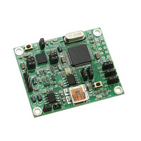
BOARD EVAL GYRO LY550ALH
Manufacturer
STMicroelectronics
Series
MEMSr
Datasheet
1.STEVAL-MKI034V1.pdf
(34 pages)
Specifications of STEVAL-MKI041V1
Sensor Type
Gyroscope, 2 Axis
Sensing Range
±500°/sec
Interface
Analog
Sensitivity
2mV/°/s
Embedded
No
Utilized Ic / Part
LY550ALH
Interface Type
USB
Lead Free Status / RoHS Status
Lead free by exemption / RoHS compliant by exemption
Voltage - Supply
-
Lead Free Status / Rohs Status
Lead free / RoHS Compliant
For Use With/related Products
ST72651AR6
Other names
497-10172


UM0796
2
2.1
Working modes
The STEVAL-MKI0xxV1 demonstration board is designed to be used in two different
working modes:
- Analog working mode (AWM): the microcontroller on the board is disabled and the analog
outputs of the device are available to the user on the dedicated connector
This is the default working mode when power is applied either through the USB connector or
through the supply connector
-Digital working mode (DWM): the microcontroller on the board is enabled and allows the
user to digitally acquire the output signals of the device, to see them on the PC through the
dedicated GUI and to manage the control pins of the device.
Each working mode requires a board setup, which is done by correctly setting the jumpers
labeled JP4, JP5, JP7 (see ref 1, ref 2 and ref 3, respectively, in
labeled JP1 and JP6 (see ref 4 and ref 5, respectively, in
Analog working mode (AWM)
AWM is the working mode activated by default when the board is connected to a PC by USB
or when the power supply is applied to J10. The microcontroller on the board is disabled and
board behavior can be controlled through the dedicated jumpers.
In this working mode, the power down (PD), self-test (ST) and high-pass filter reset (HP)
functions are respectively managed by JP4, JP5 and JP7 as described below (see
to identify the jumpers):
Table 1.
Analog output signals can be measured respectively through pin 3 (marked Out1), pin 4
(marked Out2, for single-axis devices only) and pin1 (GND) of the J3 header (see
ref 7).
The JP1 and JP6 jumpers allow the user to select which output signal is available on J3.
JP4
JP5
JP7
PD
HP
ST
Logic level 1: external high-pass filter reset
Jumper configurations for power down (PD), self-test (ST) and high pass
filter reset (HP) in AWM
Logic level 1: power down mode
Logic level 1: self-test ON
Jumper on 1-2 position
(Figure
Doc ID 16227 Rev 1
3, ref 10).
Logic level 0: normal mode, default
Logic level 0: normal mode, default
Logic level 0: self-test OFF, default
Figure
Jumper on 2-3 position
3).
Figure
3) and the jumpers
(Figure
Working modes
3, ref 7).
Figure
Figure 3
7/34
3,
Related parts for STEVAL-MKI041V1
Image
Part Number
Description
Manufacturer
Datasheet
Request
R

Part Number:
Description:
BOARD EVAL FOR MEMS SENSORS
Manufacturer:
STMicroelectronics
Datasheet:

Part Number:
Description:
EVALBOARD/STEVAL-ISV014V1
Manufacturer:
STMicroelectronics
Part Number:
Description:
BOARD EVAL FOR ST802RT1
Manufacturer:
STMicroelectronics
Datasheet:

Part Number:
Description:
BOARD EVAL FOR VACUUM CLEANER
Manufacturer:
STMicroelectronics
Datasheet:

Part Number:
Description:
KIT DEV STARTER ST10F276Z5
Manufacturer:
STMicroelectronics
Datasheet:

Part Number:
Description:
BOARD LED CTLR/DVR STLED316S
Manufacturer:
STMicroelectronics
Datasheet:

Part Number:
Description:
BOARD EVAL BLDC SENSORLESS MOTOR
Manufacturer:
STMicroelectronics
Datasheet:

Part Number:
Description:
BOARD ELECT FISCAL CASH REGISTER
Manufacturer:
STMicroelectronics
Datasheet:

Part Number:
Description:
BOARD EVAL BIPO SOLUTION FOR PFC
Manufacturer:
STMicroelectronics
Datasheet:

Part Number:
Description:
BOARD EVAL UPS 450W VOUT=220V
Manufacturer:
STMicroelectronics
Datasheet:
Part Number:
Description:
STMicroelectronics [RIPPLE-CARRY BINARY COUNTER/DIVIDERS]
Manufacturer:
STMicroelectronics
Datasheet:
Part Number:
Description:
STMicroelectronics [LIQUID-CRYSTAL DISPLAY DRIVERS]
Manufacturer:
STMicroelectronics
Datasheet:
Part Number:
Description:
BOARD EVAL FOR MEMS SENSORS
Manufacturer:
STMicroelectronics
Datasheet: