BMA140-SHUTL Bosch Sensortec, BMA140-SHUTL Datasheet - Page 15
BMA140-SHUTL
Manufacturer Part Number
BMA140-SHUTL
Description
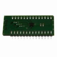
BMA140 DAUGHTERCARD FOR DEV KIT
Manufacturer
Bosch Sensortec
Specifications of BMA140-SHUTL
Sensor Type
Accelerometer, 3 Axis
Sensing Range
±2g, 4g, 8g
Interface
Analog
Sensitivity
0.300 V/g
Voltage - Supply
1.8 V ~ 3.5 V
Embedded
No
Utilized Ic / Part
BMA140
For Use With
DM240021 - KIT STARTER MPLAB FOR PIC24H
Lead Free Status / RoHS Status
Contains lead / RoHS non-compliant
Other names
828-1010


4.8
The following external components (c
The typical bandwidth of the sensor module without subsequent RC low pass filtering is 1.5kHz.
According to the following equation a customized cut-off frequency can be realized by a simple
dimension of C
to the x-axis but it is also representative for the y- and z-axis. The AMUX cut-off frequency
output behavior is directly linked up to C
capacitor on the multiplexer output pin.
4.9
Micromechanical sensors are designed to sense acceleration with high accuracy even at low
amplitudes and contain highly sensitive structures inside the sensor element. The MEMS sensor
can tolerate mechanical shocks up to several thousand g’s. However, these limits might be
exceeded in conditions with extreme shock loads such as e.g. hammer blow on or next to the
sensor, dropping of the sensor onto hard surfaces etc.
We strongly recommend to avoid g-forces beyond the specified limits (see section 2) during
transport, handling and mounting of the sensors in a defined and qualified installation process.
This device has built-in protections against high electrostatic discharges or electric fields (e.g.
2kV HBM); however, anti-static precautions should be taken as for any other CMOS component.
Unless otherwise specified, proper operation can only occur when all terminal voltages are kept
within the supply voltage range. Unused inputs must always be tied to a defined logic voltage
level. Please refer to the separately available document “Handling, soldering & mounting
instructions” for the BMA140.
Rev. 1.1
© Bosch Sensortec GmbH reserves all rights even in the event of industrial property rights. We reserve all rights of disposal such
as copying and passing on to third parties. BOSCH and the symbol are registered trademarks of Robert Bosch GmbH, Germany.
Note: Specifications within this document are subject to change without notice.
Connecting diagram
Handling instructions
x
(C
y
C
, C
x
z
) to create a RC low pass filter. The below given equation corresponds
Triaxial, analog acceleration sensor
33 kΩ
33 kΩ
33 kΩ
f
c
_
x
1
AX
AY
AZ
AMUX
=
and c
2
π
Data sheet
Page 15
x ,
BMA140
⋅
2
33
V
V
GND
) are recommended to decouple the power source.
C
DDA
DDD
1
k
y
Ω
& C
⋅
c
x
z .
100nF
C
Do not connect an additional external
1
3.0 V
10nF
C
2
Bosch Sensortec
04 April 2008
Related parts for BMA140-SHUTL
Image
Part Number
Description
Manufacturer
Datasheet
Request
R

Part Number:
Description:
3-AXIS ACCELEROMETER ANALOG I/F
Manufacturer:
Bosch Sensortec
Datasheet:

Part Number:
Description:
DEVELOPMENT BOARD FOR SENSOR ICS
Manufacturer:
Bosch Sensortec

Part Number:
Description:
BMA150 DAUGHTERCARD FOR DEV KIT
Manufacturer:
Bosch Sensortec
Datasheet:

Part Number:
Description:
BMA020 DAUGHTERCARD FOR DEV KIT
Manufacturer:
Bosch Sensortec

Part Number:
Description:
BMA020 TRIBOX DEMO BOARD W/USB
Manufacturer:
Bosch Sensortec

Part Number:
Description:
BMA150 TRIBOX DEMO BOARD W/USB
Manufacturer:
Bosch Sensortec
Datasheet:

Part Number:
Description:
BMA145 DAUGHTERCARD FOR DEV KIT
Manufacturer:
Bosch Sensortec
Datasheet:

Part Number:
Description:
DAUGHTERCARD FOR DEV KIT BMA120
Manufacturer:
Bosch Sensortec
Datasheet:

Part Number:
Description:
DAUGHTERCARD FOR DEV KIT BMA220
Manufacturer:
Bosch Sensortec
Datasheet:

Part Number:
Description:
BMP085 DAUGHTERCARD FOR DEV KIT
Manufacturer:
Bosch Sensortec
Datasheet:

Part Number:
Description:
DIGITAL BAROMETRIC PRESSURE SNSR
Manufacturer:
Bosch Sensortec
Datasheet:

Part Number:
Description:
ABS. PRESSURE SENSOR ANLG INDUST
Manufacturer:
Bosch Sensortec
Datasheet:

Part Number:
Description:
ACCELEROMETER 3-AXIS SPI/I2C SMD
Manufacturer:
Bosch Sensortec
Datasheet:

Part Number:
Description:
ACCELEROMETER 3-AXIS SPI/I2C SMD
Manufacturer:
Bosch Sensortec
Datasheet:

Part Number:
Description:
3-AXIS ACCELEROMETER DIGITAL I/F
Manufacturer:
Bosch Sensortec
Datasheet: