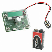
AS5163 DB austriamicrosystems, AS5163 DB Datasheet - Page 30

AS5163 DB
Manufacturer Part Number
AS5163 DB
Description
BOARD DEMO AS5163
Manufacturer
austriamicrosystems
Specifications of AS5163 DB
Sensor Type
Magnetic, Rotary Position
Sensing Range
360°
Interface
Serial
Voltage - Supply
Battery, 9V
Embedded
Yes, MCU, 8-Bit
Utilized Ic / Part
AS5163
Lead Free Status / RoHS Status
Lead free by exemption / RoHS compliant by exemption
Sensitivity
-
AS5163
Datasheet - A p p l i c a t i o n I n f o r m a t i o n
8.2.1 Read / Write User Data
Table 17. Read / Write Data
Data Content:
Data only for read:
Data for write and read:
8.2.2 Programming Procedure
Note: After programming the OTP fuses, a verification is mandatory. The procedure described below must be strictly followed to ensure
For further information, please refer to Application Note AN5163-10 available at
www.austriamicrosystems.com/AS5163
Read and Write
Region
Read only
Area
CORDIC_OUT(13:0): 14-bit absolute angular position data.
OCF (Offset Compensation Finished): logic high indicates the finished Offset Compensation Algorithm. As soon as this bit is set, the
AS5163 has completed the startup and the data is valid.
COF (Cordic Overflow): Logic high indicates an out of range error in the CORDIC part. When this bit is set, the CORDIC_OUT(13:0) data is
invalid. The absolute output maintains the last valid angular value. This alarm may be resolved by bringing the magnet within the X-Y-Z
tolerance limits.
AGC_VALUE (7:0): magnetic field indication.
DSP_RES resets the DSP part of the AS5163 the default value is 0. This is active low. The interface is not affected by this reset.
R1K_10K defines the threshold level for the OTP fuses. This bit can be changed for verification purpose. A verification of the programming
of the fuses is possible. The verification is mandatory after programming.
Pull-up / Pull-down on OUT pin
VDD=5V
Wait startup time, device enters communication mode
Write128 command: The trimming bits are written in the SFR memory.
Read128 command: The trimming bits are read back.
Upload command: The SFR memory is transferred into the OTP RAM.
Fuse command: The OTP RAM is written in the Poly Fuse cells.
Wait fuse time (6 ms)
Write command (R1K_10K=1): Poly Fuse cells are transferred into the RAM cells compared with 10KΩ resistor.
Download command: The OTP RAM is transferred into the SFR memory.
Read128 command: The fused bits are read back.
Write command (R1K_10K=0): Poly Fuse cells are transferred into the RAM cells compared with 1KΩ resistor.
Download command: The OTP RAM is transferred into the SFR memory.
Read128 command: The fused bits are read back.
Pass2Func command or POR: Go to Functional mode.
properly programmed OTP fuses.
Address
0x10
0x11
0x12
0x17
Address
16
17
18
23
OCF
Bit7
0
COF
Bit6
0
Revision 2.7
Bit5
0
www.austriamicrosystems.com
CORDIC_OUT[7:0]
AGC_VALUE[7:0]
Bit4
0
CORDIC_OUT[13:8]
Bit3
0
Bit2
0
DSP_RES R1K_10K
Bit1
Bit0
30 - 36


