MCP9700DM-PCTL Microchip Technology, MCP9700DM-PCTL Datasheet - Page 12
MCP9700DM-PCTL
Manufacturer Part Number
MCP9700DM-PCTL
Description
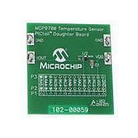
BOARD DEMO FOR PICTAIL MCP9700
Manufacturer
Microchip Technology
Series
PICtail™r
Specifications of MCP9700DM-PCTL
Sensor Type
Temperature
Sensing Range
-40°C ~ 125°C
Interface
Analog
Sensitivity
±1°C
Voltage - Supply
2.3 V ~ 5.5 V
Embedded
No
Utilized Ic / Part
MCP9700
Processor To Be Evaluated
MCP9700
Lead Free Status / RoHS Status
Contains lead / RoHS non-compliant
Lead Free Status / RoHS Status
Lead free / RoHS Compliant, Contains lead / RoHS non-compliant
Available stocks
Company
Part Number
Manufacturer
Quantity
Price
Company:

Part Number:
MCP9700DM-PCTL
Manufacturer:
Microchip Technology
Quantity:
135


FIGURE 2-2:
FIGURE 2-3:
DS51542B-page 8
USB Cable
2.3.1
1. Connect the P1 header of the MCP9700 Temperature-to-Voltage Converter
2. Insert the PIC16F676 into the evaluation socket of the PICkit 1 Flash Starter Kit
3. Connect the PICkit 1 Flash Starter Kit USB cable from the USB port of the PC to
MCP9700 PICtail™ Demo Board and PICkit™ 1 Flash Starter Kit.
Simplified MCP9700 PICtail™ Demo Board Schematic.
To ADC RC0
PICtail™ Demo Board to the J3 connector on the PICkit 1 Flash Starter Kit
board. Refer to Figure 2-2 for proper orientation of the MCP9700 Tempera-
ture-to-Voltage Converter PICtail™ Demo Board and Figure 2-3 for the
simplified board schematic.
board.
the USB port (J1) on the PICkit 1 Flash Starter Kit board. +5V power is supplied
to the PICkit 1 Flash Starter Kit board via the USB cable. The green POWER LED
and the red BUSY LED will turn on, indicating that power is being supplied to the
board.
Flash Starter Kit
LED D7
PICkit™ 1
GND
+5V
Hardware Setup
Expansion
Header (J3)
J3
13
14
10
MCP9700 PICtail™ Demo Board
P1
13
10
14
MCP9700 PICtail™ Demo Board
LED D0
(SC70-5)
2
PICkit™ 1 Flash Starter Kit
V
OUT
V
V
1
3
U1
DD
SS
Insert PIC16F676
© 2006 Microchip Technology Inc.
C1
0.1 µF
Related parts for MCP9700DM-PCTL
Image
Part Number
Description
Manufacturer
Datasheet
Request
R

Part Number:
Description:
BOARD DEMO THERMISTOR MCP9700
Manufacturer:
Microchip Technology
Datasheet:

Part Number:
Description:
Manufacturer:
Microchip Technology Inc.
Datasheet:
Part Number:
Description:
Manufacturer:
Microchip Technology Inc.
Datasheet:
Part Number:
Description:
Manufacturer:
Microchip Technology Inc.
Datasheet:
Part Number:
Description:
Manufacturer:
Microchip Technology Inc.
Datasheet:
Part Number:
Description:
Manufacturer:
Microchip Technology Inc.
Datasheet:
Part Number:
Description:
Manufacturer:
Microchip Technology Inc.
Datasheet:
Part Number:
Description:
Manufacturer:
Microchip Technology Inc.
Datasheet:
Part Number:
Description:
Manufacturer:
Microchip Technology Inc.
Datasheet: