DM183026 Microchip Technology, DM183026 Datasheet - Page 28
DM183026
Manufacturer Part Number
DM183026
Description
KIT EVALUATION PIC16F/PIC24F
Manufacturer
Microchip Technology
Series
mTouch™r
Datasheet
1.DM183026.pdf
(44 pages)
Specifications of DM183026
Sensor Type
Touch, Capacitive
Embedded
Yes, Other
Utilized Ic / Part
PIC16F727, PIC24FJ128GB106
Processor To Be Evaluated
PIC16F, PIC24F
Interface Type
USB
Silicon Manufacturer
Microchip
Kit Application Type
Sensing - Touch / Proximity
Application Sub Type
Capacitive Touch
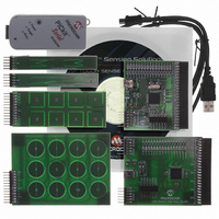
Kit Contents
6x Brds, Analyser, Cable, CD
Lead Free Status / RoHS Status
Lead free / RoHS Compliant
Voltage - Supply
-
Interface
-
Sensitivity
-
Sensing Range
-
Lead Free Status / Rohs Status
Lead free / RoHS Compliant
Available stocks
Company
Part Number
Manufacturer
Quantity
Price
Company:

Part Number:
DM183026
Manufacturer:
Microchip Technology
Quantity:
135
Company:
Part Number:
DM183026-2
Manufacturer:
Microchip Technology
Quantity:
135
Company:
Part Number:
DM183026-2
Manufacturer:
MICROCHIP
Quantity:
12 000


mTouch™ Capacitive Evaluation Kit User’s Guide
FIGURE 4-2:
DS41385A-page 24
I
PLUG-IN BOARDS
2
Direct Key Slider
C™ PICKit Serial
Programming
Plug-in
Slider Plug-in
Slider Plug-in
Key Plug-in
2-Channel
8-Channel
4-Channel
Header
Header
Matrix
Board
Board
Board
J2
J1
Board
The CAP TOUCH – CTMU Evaluation Board comprises 16 A/D channels of the PIC24F
microcontroller connected to connector, J4. This connector is used to interface the
plug-in boards to the evaluation board.
The plug-in boards can be connected to any of the 16 channels of the connector (14)
by changing the configuration settings, which is explained in the Readme.txt file.
A total of 16 LEDs are provided in the CAP TOUCH – CTMU Evaluation Board. These
LEDs are driven directly by the microcontroller through pins on PORTD and PORTE.
When an event occurs, the application firmware also provides feedback by activating
one or more LEDs at that location. The sequence for the activation of the LEDs
depends on the type of touch pads that is interfaced to the evaluation board.
The microcontroller uses its on-chip USB engine and transceiver to communicate to the
PC side interface application, using the USB mini-B receptacle. The demo board also
uses the USB receptacle for application power as a bus-powered device.
Microcontroller and LED power are provided from the V
voltage regulator. Provisions on the board allow for users to add components and
create an externally powered application.
For users interested in using the CAP TOUCH – CTMU Evaluation Board as an
experimental platform, the microcontroller can be reprogrammed using the ICSP™
connector. A 6-pin header is provided for connecting the demo board to any MPLAB
ICD 2 compatible programmer. Since the ICD interface (PGD and PGC) shares some
input channels of the connector J4 (channel 6 and 7), necessary care should be taken
when the debugger is enabled.
The firmware in the CAP TOUCH-CTMU Evaluation Board will have the default plug-in
board channel configurations, which is explained in the Readme.txt file. The user can
reconfigure the channels based on his application by referring to the Readme.txt file.
APPLICATION SIDE BLOCK DIAGRAM FOR THE CSM BOARD
ICSP™
I
2
C™
J4
CPS15:0
ICSPDAT
ICSPCLK
MCLR
V
V
DD
SS
CAP TOUCH – CSM EVALUATION BOARD
PIC16F727
GPIO
V
Vss
DD
J5
BUS
© 2009 Microchip Technology Inc.
16 LEDs (D1-D16)
by Q1, an MCP1702
Sensor Boards
USB mini-B
Receptacle
Related parts for DM183026
Image
Part Number
Description
Manufacturer
Datasheet
Request
R

Part Number:
Description:
Manufacturer:
Microchip Technology Inc.
Datasheet:
Part Number:
Description:
Manufacturer:
Microchip Technology Inc.
Datasheet:
Part Number:
Description:
Manufacturer:
Microchip Technology Inc.
Datasheet:
Part Number:
Description:
Manufacturer:
Microchip Technology Inc.
Datasheet:
Part Number:
Description:
Manufacturer:
Microchip Technology Inc.
Datasheet:
Part Number:
Description:
Manufacturer:
Microchip Technology Inc.
Datasheet:
Part Number:
Description:
Manufacturer:
Microchip Technology Inc.
Datasheet:
Part Number:
Description:
Manufacturer:
Microchip Technology Inc.
Datasheet: