DM183026-2 Microchip Technology, DM183026-2 Datasheet - Page 19
DM183026-2
Manufacturer Part Number
DM183026-2
Description
KIT EVAL MTOUCH CAPACTIVIE
Manufacturer
Microchip Technology
Series
mTouch™r
Datasheet
1.DM183026-2.pdf
(54 pages)
Specifications of DM183026-2
Sensor Type
Touch, Capacitive
Sensing Range
8 & 12 Buttons/Keys, 2 Sliders
Interface
I²C
Voltage - Supply
5V, USB
Embedded
Yes
Utilized Ic / Part
PIC16F, PIC18F, PIC24F, PIC32MX
Interface Type
USB, I2C, UART
Operating Voltage
5 V
Data Bus Width
32 bit
Silicon Manufacturer
Microchip
Kit Application Type
Sensing - Touch / Proximity
Application Sub Type
Capacitive Touch
Kit Contents
8x Brds, Serial Anaylizer, USB Cable
For Use With/related Products
PIC16F, PIC24F, PIC18F, PIC32
Lead Free Status / RoHS Status
Lead free / RoHS Compliant
Sensitivity
-
Lead Free Status / Rohs Status
Lead free / RoHS Compliant
Available stocks
Company
Part Number
Manufacturer
Quantity
Price
Company:

Part Number:
DM183026-2
Manufacturer:
Microchip Technology
Quantity:
135
Company:
Part Number:
DM183026-2
Manufacturer:
MICROCHIP
Quantity:
12 000


© 2010 Microchip Technology Inc.
2.2.2
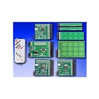
The Matrix Key Plug-in daughter board is an array of 12 touch-sensitive keys arranged
in a 4x3 matrix. Touching any one of the keys will light up one of the LEDs. Here, the
Matrix Key Plug-in daughter board is numbered, 0 to 11, which corresponds to LEDs
D1 to D12, respectively.
The default firmware loaded in the mTouch Advanced Capacitive Evaluation Kit for the
Matrix Key Plug-in daughter board is configured for channels 8 to 14 in PIC16F CSM,
PIC24F CTMU, PIC24H CVD and PIC32MX CVD evaluation boards, and channels 6
to 12 in PIC18F CTMU evaluation boards.
When the key numbered ‘0’ is pressed, the LED D1 will be lit. Similarly, when the keys
numbered ‘1’ to ‘11’ are pressed, the LEDs D2 through D12 will be lit, respectively.
Here, one LED will be lit for every press of the key on the plug-in board.
2.2.3
Touching anywhere along the length of the slider causes all the LEDs to light up as a
bar graph that is representative to the position of the touch. The LED bar graph follows
the finger as it moves up and down along the length of the slider, and remains at the
last position on the slider when the finger is removed.
The default firmware for the 2-Channel Slider Plug-in, loaded in the evaluation kit, is
configured such that, the channels 0 and 1 of connector J4/J3 in the evaluation kit are
connected to the 2-Channel Slider Plug-in daughter board.
The default firmware for the 4-Channel Slider Plug-in, loaded in the evaluation kit, is
configured such that, channels 0, 1, 2 and 3 of connector J4/J3 in the main evaluation
board are connected to the 4 channels in the 4-Channel Slider Plug-in daughter board
(see Figure 2-2).
FIGURE 2-2:
Note 1:
2:
12-Key Matrix Plug-in Daughter Board
2-Channel and 4-Channel Slider Plug-in Daughter Board
The plug-in boards can be interfaced to any of the channels in the
evaluation kit by changing the configuration settings. The details of the
configuration settings are explained in the Readme.txt file, which is
distributed in each demonstration.
Plugging a sensor board in while an evaluation board is running, may
require resetting the touch algorithm, most easily done by cycling power.
DEFAULT PLUG-IN CHANNELS FOR 4-CHANNEL SLIDER
PLUG-IN BOARD
Demonstration Application
DS41385C-page 19
Related parts for DM183026-2
Image
Part Number
Description
Manufacturer
Datasheet
Request
R

Part Number:
Description:
Manufacturer:
Microchip Technology Inc.
Datasheet:
Part Number:
Description:
Manufacturer:
Microchip Technology Inc.
Datasheet:
Part Number:
Description:
Manufacturer:
Microchip Technology Inc.
Datasheet:
Part Number:
Description:
Manufacturer:
Microchip Technology Inc.
Datasheet:
Part Number:
Description:
Manufacturer:
Microchip Technology Inc.
Datasheet:
Part Number:
Description:
Manufacturer:
Microchip Technology Inc.
Datasheet:
Part Number:
Description:
Manufacturer:
Microchip Technology Inc.
Datasheet:
Part Number:
Description:
Manufacturer:
Microchip Technology Inc.
Datasheet: