DM240002 Microchip Technology, DM240002 Datasheet - Page 30
DM240002
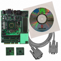
Manufacturer Part Number
DM240002
Description
BOARD DEV EXPLORER 16 44-PIN
Manufacturer
Microchip Technology
Series
Explorer 16 44-pinr
Type
MCUr
Datasheet
1.DM240002.pdf
(42 pages)
Specifications of DM240002
Contents
Explorer 16 Dev Board, PIC24FJ64GA004 and dsPIC33FJ32GP204 PIM Modules
Processor To Be Evaluated
PIC24FJ128GA010, dsPIC33FJ256GP710
Processor Series
PIC 24, dsPIC33
Data Bus Width
32 bit
Interface Type
RS-232
Silicon Manufacturer
Microchip
Core Architecture
PIC, DsPIC
Core Sub-architecture
PIC24, DsPIC33
Silicon Core Number
PIC24F, DsPIC33F
Lead Free Status / RoHS Status
Lead free / RoHS Compliant
For Use With/related Products
dsPIC30, dsPIC33, PIC32, PIC24FJ, PIC24HJ
Lead Free Status / Rohs Status
Lead free / RoHS Compliant
Available stocks
Company
Part Number
Manufacturer
Quantity
Price
Company:

Part Number:
DM240002
Manufacturer:
Microchip Technology
Quantity:
135
Company:
Part Number:
DM240002
Manufacturer:
MICROCHIP
Quantity:
12 000


44-Pin Demo Board User’s Guide
DS41296B-page 26
3.2.8
Lesson 8 shows the reversible LEDs but with the Delay Loop rewritten as a function.
New Instructions
Functions or Subroutines are invoked with the CALL instruction and terminated with
a RETURN or RETLW instruction. RETURN jumps back to the original program at the
location following the CALL. RETLW also returns to the calling program, but loads the
WREG with a constant.
The mid-range PIC
addresses.
If a ninth CALL is made, it will overwrite the first one and then the program will not be
able to RETURN all the way back.
Passing Arguments
Arguments to the subroutine may be passed in a number of ways. WREG is a conve-
nient place to pass one byte and the FSR may be used to pass another byte, if not oth-
erwise used. If more data must be passed, a buffer must be allocated.
When the Delay function is pulled out to a subroutine, the ADC result is moved into
WREG, then the CALL transfers control to the Delay subroutine. The RETURN trans-
fers control to the MOVLW following the CALL.
EXAMPLE 3-7:
3.2.9
Timer0 is a counter implemented in the processor. It may be used to count processor
clock cycles or external events. Lesson 9 configures it to count instruction cycles and
set a flag when it rolls over. This frees up the processor to do meaningful work rather
than just counting cycles for a delay.
Timer0 is an 8-bit counter with an optional prescaler, which is configured to divide by
256 before reaching the Timer0 counter.
...
; Delay Function.
Delay:
DelayLoop:
CALL
RETURN
RETLW
MOVF
ADDLW
CALL
GOTO
MOVWF
DECFSZ
GOTO
DECFSZ
GOTO
RETURN
Lesson 8: Function Calls
Lesson 9: Timer0
ADRESH,w
1
Delay
XXX
Delay2
Delay1,f
DelayLoop
Delay2,f
DelayLoop
; goes back to instruction after call
®
FUNCTION CALL EXAMPLE
microcontroller device’s CALL stack can hold up to 8 return
Invokes functions or subroutines
Terminates functions or subroutines
Terminates functions or subroutines
Enter with number of 771uS delays in Wreg
; Move conversion value (delay) to w
; add 1 otherwise entering with 0 takes
; longer than entering with 1.
; Call delay function
; returns here when done
© 2007 Microchip Technology Inc.
Related parts for DM240002
Image
Part Number
Description
Manufacturer
Datasheet
Request
R

Part Number:
Description:
Manufacturer:
Microchip Technology Inc.
Datasheet:
Part Number:
Description:
Manufacturer:
Microchip Technology Inc.
Datasheet:
Part Number:
Description:
Manufacturer:
Microchip Technology Inc.
Datasheet:
Part Number:
Description:
Manufacturer:
Microchip Technology Inc.
Datasheet:
Part Number:
Description:
Manufacturer:
Microchip Technology Inc.
Datasheet:
Part Number:
Description:
Manufacturer:
Microchip Technology Inc.
Datasheet:
Part Number:
Description:
Manufacturer:
Microchip Technology Inc.
Datasheet:
Part Number:
Description:
Manufacturer:
Microchip Technology Inc.
Datasheet: