Z8F04A08100KIT Zilog, Z8F04A08100KIT Datasheet
Z8F04A08100KIT
Specifications of Z8F04A08100KIT


Related parts for Z8F04A08100KIT


Z8F04A08100KIT Summary of contents
Page 1
... Z8 Encore! XP Z8F04A08100KIT Z8 Encore! XP 8-Pin Development Kit User Manual UM018702-0505 ZiLOG Worldwide Headquarters • 532 Race Street • San Jose, CA 95126 Telephone: 408.558.8500 • Fax: 408.558.8300 • ® Microcontroller Family ® 4K Series www.ZiLOG.com ...
Page 2
... Document Disclaimer ZiLOG is a registered trademark of ZiLOG Inc. in the United States and in other countries. All other products and/or service names mentioned herein may be trademarks of the companies with which they are associated. ©2005 by ZiLOG, Inc. All rights reserved. Information in this publication concerning the devices, applications, or technology described is intended to suggest possible uses and may be superseded ...
Page 3
... Features . . . . . . . . . . . . . . . . . . . . . . . . . . . . . . . . . . . . . . . . . . . . . . . . . . . . .8 MCU . . . . . . . . . . . . . . . . . . . . . . . . . . . . . . . . . . . . . . . . . . . . . . . . . . . . . . .8 UART with IrDA Endec . . . . . . . . . . . . . . . . . . . . . . . . . . . . . . . . . . . . . . . .9 Jumpers and Settings . . . . . . . . . . . . . . . . . . . . . . . . . . . . . . . . . . . . . . . . . .10 DEMO Mode Jumper Settings . . . . . . . . . . . . . . . . . . . . . . . . . . . . . . .11 USER DEBUG Mode Jumper Settings . . . . . . . . . . . . . . . . . . . . . . . .12 Switches S1, S2, and SW1 . . . . . . . . . . . . . . . . . . . . . . . . . . . . . . . . . . . . .12 External Interface Headers JP1 and JP2 . . . . . . . . . . . . . . . . . . . . . . . . . . .12 Use of Ceramic Resonator .13 Schematic . . . . . . . . . . . . . . . . . . . . . . . . . . . . . . . . . . . . . . . . . . . . . . . . . . . . .15 UM018702-0505 Z8F04A08100KIT Development Kit User Manual Table of Contents iii ...
Page 4
... Z8F04A08100KIT Development Kit User Manual iv Table of Contents UM018702-0505 ...
Page 5
... List of Figures Figure 1. Figure 2. UM018702-0505 Z8F04A08100KIT Development Kit Z8 Encore! XP® 4K Series 8-Pin Development Kit Contents (Printed Quick Start Guide Not Shown Encore! XP® 4K Series 8-Pin Development Board . . . .7 User Manual v List of Figures ...
Page 6
... Z8F04A08100KIT Development Kit User Manual vi List of Figures UM018702-0505 ...
Page 7
... The Z8 Encore! XP microcontroller products. The Z8 Encore! XP (Z8F04A08100KIT) enables users to become familiar with the hardware and software tools available with this product. This kit consists of the 4KB version of the Z8 Encore! Development board that supports and pre- sents the features of the Z8 Encore Series 8-pin package. This kit allows users to begin writing application software and contains all sup- porting documents ...
Page 8
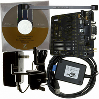
... Z8F04A08100KIT Development Kit User Manual 2 Packaging Development Board Figure 1. Z8 Encore! XP Software (on CD-ROM) • ZDS II- Z8 Encore! • Sample code • Document browser • Acrobat Reader install program Introduction Power Supply ® 4K Series 8-Pin Development Kit Contents (Printed Quick Start Guide Not Shown) ® ...
Page 9
... IBM PC (or compatible computer) with the following minimum configu- rations: Supported Host System Configuration • Win98 Second Edition, Win2000 Service Pack 3, WinXP Profes- sional Service Pack 1 • PentiumII/233MHz processor or higher up to Pentium IV, 2.8 GHz • RAM or more UM018702-0505 Z8F04A08100KIT Development Kit in the user's disk drive. User Manual 3 <installa- Introduction ...
Page 10
... Designing with the USB Smart Cable The Z8 Encore Series 8-Pin Development Kit requires use of the USB Smart Cable (supplied). The Z8 Encore! Serial Smart Cable and associated TIM will not work with the Z8F04A08100KIT kit. When designing your target board and application: • ...
Page 11
... Installation Follow the directions in the Quick Start Guide (QS0043) for software installation and setup of the Z8 Encore Series 8-Pin Development kit. UM018702-0505 Z8F04A08100KIT Development Kit User Manual 5 Installation ...
Page 12
... Z8F04A08100KIT Development Kit User Manual 6 Installation UM018702-0505 ...
Page 13
... The board provides customers with a tool to evaluate features of Z8 Encore Series 8-Pin MCU, and to start developing an application before building the hardware. Resonator not installed on production units. Figure 2. Z8 Encore! XP UM018702-0505 Z8F04A08100KIT Development Kit ® 4K Series 8-Pin Development board is a develop- ® 4K Series 8-Pin Development Board User Manual 7 DBG Pin 1 ...
Page 14
... Z8F04A08100KIT Development Kit User Manual 8 Features • Z8 Encore! • 3 LEDs • RS-232 interface • IrDA transceiver • Two pushbuttons, RESET and TEST • 5 VDC power connector • On-Chip Debugger interface • Prototyping area • External interface connectors JP1 and JP2 • ...
Page 15
... Z8 Encore! XP™ 4K Series 8- pin MCU and IrDA transceivers. Infrared communication provides secure, reliable, low-cost, point-to-point communication between PCs, PDAs, cell phones, printers and other infrared enabled devices. UM018702-0505 Z8F04A08100KIT Development Kit User Manual ® family of devices, consult the Development Board ...
Page 16
... Z8F04A08100KIT Development Kit User Manual 10 Jumpers and Settings Table 1 provides information on jumper functions. Table 1. Z8F04A08100KIT Jumper Functions Jumper State J1* OUT IN J2* OUT IN J3 1-2 2-3 J4 OUT IN J5 1-2 2-3 J6 1-2 2-3 Development Board Description Enables RS-232 interface Disables RS-232 interface Enables IrDA interface ...
Page 17
... Table 1. Z8F04A08100KIT Jumper Functions Jumper State J7 OUT IN J8 1-2 2-3 J9 1-2 2-3 J10 1-2 2-3 J11 OUT IN Note: * These jumpers must not be OUT at the same time The board has two modes of operation: DEMO and USER. Use DEMO mode to run the sample program included with the kit. Run the board in USER mode: • ...
Page 18
... Z8F04A08100KIT Development Kit User Manual 12 J3 1-2 J4 OUT J5 1-2 J6 1-2 J7 OUT J8 1-2 J9 1-2 J10 1-2 J11 OUT USER DEBUG Mode Jumper Settings When running the board in USER DEBUG mode, the following jumpers MUST be set: J3 OUT OUT J7 IN Switches S1, S2, and SW1 Switches S1, S2, and SW1 on the Z8 Encore! XP™ ...
Page 19
... Use of Ceramic Resonator Y1 When using ceramic resonator Y1, pins PA0, PA1, and DBG are unavail- able to the user. For more information, refer to the Z8 Encore! XP™ 4K Series Product Specification, PS0228. UM018702-0505 Z8F04A08100KIT Development Kit User Manual Development Board 13 ...
Page 20
... Z8F04A08100KIT Development Kit User Manual 14 Development Board UM018702-0505 ...
Page 21
... Schematic This section includes schematics for the Z8 Encore Series 8-Pin Development Board. UM018702-0505 Z8F04A08100KIT Development Kit User Manual 15 Schematic ...
Page 22
... UM018702-0505 Z8F04A08100KIT Development Kit User Manual 16 Schematic ...
Page 23
PWR JACK OFF C4 0.1uF SW KEY-SPDT VIN VOUT 1 GND SPX2815AU-3.3 0.1uF GND VCC_33V U3B 74LVC04/ GND VCC_33V U3C 74LVC04/SO R4 GND ...
Page 24
R11 D2 VCC_33V VCC_33V VCC_33V VCC_33V VCC_33V VCC_33V 2 VCC_33V LED 100 R12 10K S1 PA3_CTS0 1 2 GND TEST R13 D3 2 LED 100 R15 D4 2 LED 100 PA0_JP C13 PA1_JP R16 R17 8 pin footprint U5 0 ...