DK-START-4CGX15N Altera, DK-START-4CGX15N Datasheet - Page 22
DK-START-4CGX15N
Manufacturer Part Number
DK-START-4CGX15N
Description
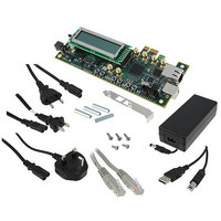
KIT STARTER CYCLONE IV GX
Manufacturer
Altera
Series
Cyclone® IVr
Type
FPGAr
Specifications of DK-START-4CGX15N
Contents
Board, Cables, Power Supply
Silicon Manufacturer
Altera
Core Architecture
FPGA
Core Sub-architecture
Cyclone
Silicon Core Number
EP4C
Silicon Family Name
Cyclone IV GX
Kit Contents
Board, Cables, PSU, CD
Rohs Compliant
Yes
For Use With/related Products
Cyclone IV GX
Lead Free Status / RoHS Status
Lead free / RoHS Compliant
Other names
544-2569
Available stocks
Company
Part Number
Manufacturer
Quantity
Price
Company:

Part Number:
DK-START-4CGX15N
Manufacturer:
Altera
Quantity:
135


6–4
The General Tab
Cyclone IV GX Transceiver Starter Kit User Guide
c
Figure 6–2. The Configure Menu
To configure the FPGA with a test system design, perform the following steps:
1. On the Configure menu, click the configure command that corresponds to the
2. When configuration finishes, the design begins running in the FPGA. The
Board Rework Required
For the SMA tests to work correctly, you must modify your board. The Ethernet PHY
and transceiver SMA connectors use the same transceiver path. The board ships with
the transceiver path connected to the Ethernet PHY. A solder modification is required
to change the transceiver path from the Ethernet PHY to the transceiver SMA
connectors.
To avoid damage to your board, have an experienced technician perform the board
modifications.
Table 6–1
enable either the Ethernet PHY or the transceiver SMA connectors.
Table 6–1. Resistor and Capacitor Placement
The General tab shows information about the board’s current configuration.
Figure 6–1 on page 6–2
MAX II registers, the JTAG chain, the board’s MAC address, the flash memory map,
and other details stored on the board.
The following sections describe the controls on the General tab.
Board Information
The Board information controls display static information about your board.
Transceiver SMA
Ethernet
Notes to
(1) This configuration routes the transceiver channel to SMA connectors J8, J9, J10 and J11.
(2) This configuration is the factory default and routes the transceiver channel to the Ethernet PHY.
Loopback Tests
functionality you wish to test.
corresponding GUI application tabs that interface with the design enable.
Table
(2)
shows the required placement of the 0 Ω resistors and 0.1 µF capacitors to
6–1:
(1)
0.1 µF Capacitors at C57 and C60
0 Ω Resistors at R51 and R54
shows the General tab. The tab displays the contents of the
Remove
Install
0.1 µF Capacitors at C58 and C59
0 Ω Resistors at R52 and R53
© March 2010 Altera Corporation
Chapter 6: Board Test System
Using the Board Test System
Remove
Install
Related parts for DK-START-4CGX15N
Image
Part Number
Description
Manufacturer
Datasheet
Request
R

Part Number:
Description:
KIT STARTER CYCLONE III EP3C25
Manufacturer:
Altera
Datasheet:

Part Number:
Description:
Cyclone IV Tranceiver Development Kit
Manufacturer:
Altera
Datasheet:

Part Number:
Description:
Programmable Logic IC Development Tools FPGA Development Kit For 5AGXFB3H4F35C5N
Manufacturer:
Altera Corporation
Datasheet:
Part Number:
Description:
Programmable Logic IC Development Tools FPGA Starter Kit For 5AGXFB3H4F
Manufacturer:
Altera Corporation
Datasheet:

Part Number:
Description:
CYCLONE II STARTER KIT EP2C20N
Manufacturer:
Altera
Datasheet:

Part Number:
Description:
CPLD, EP610 Family, ECMOS Process, 300 Gates, 16 Macro Cells, 16 Reg., 16 User I/Os, 5V Supply, 35 Speed Grade, 24DIP
Manufacturer:
Altera Corporation
Datasheet:
Part Number:
Description:
CPLD, EP610 Family, ECMOS Process, 300 Gates, 16 Macro Cells, 16 Reg., 16 User I/Os, 5V Supply, 15 Speed Grade, 24DIP
Manufacturer:
Altera Corporation
Datasheet:
Part Number:
Description:
Manufacturer:
Altera Corporation
Datasheet:
Part Number:
Description:
CPLD, EP610 Family, ECMOS Process, 300 Gates, 16 Macro Cells, 16 Reg., 16 User I/Os, 5V Supply, 30 Speed Grade, 24DIP
Manufacturer:
Altera Corporation
Datasheet:
Part Number:
Description:
High-performance, low-power erasable programmable logic devices with 8 macrocells, 10ns
Manufacturer:
Altera Corporation
Datasheet:
Part Number:
Description:
High-performance, low-power erasable programmable logic devices with 8 macrocells, 7ns
Manufacturer:
Altera Corporation
Datasheet:
Part Number:
Description:
Classic EPLD
Manufacturer:
Altera Corporation
Datasheet:
Part Number:
Description:
High-performance, low-power erasable programmable logic devices with 8 macrocells, 10ns
Manufacturer:
Altera Corporation
Datasheet: