101-1177 Rabbit Semiconductor, 101-1177 Datasheet
101-1177
Specifications of 101-1177


Related parts for 101-1177


101-1177 Summary of contents
Page 1
RabbitCore RCM4300 C-Programmable Analog Core Module with microSD™ Card Storage and Ethernet User’s Manual 019–0163_J ...
Page 2
RabbitCore RCM4300 User’s Manual Part Number 019-0163_J • Printed in U.S.A. ©2007–2010 Digi International Inc. • All rights reserved. Digi International reserves the right to make changes and improvements to its products without providing notice. Rabbit, RabbitCore, and Dynamic C ...
Page 3
Chapter 1. Introduction 1.1 RCM4300 Features ...............................................................................................................................7 1.2 Advantages of the RCM4300 ...............................................................................................................8 1.3 Development and Evaluation Tools......................................................................................................9 1.3.1 RCM4300 Development Kit .........................................................................................................9 1.3.2 Software ......................................................................................................................................10 1.3.3 Online Documentation ................................................................................................................10 Chapter 2. Getting Started 2.1 Install Dynamic C ...............................................................................................................................11 2.2 ...
Page 4
... A.3 I/O Buffer Sourcing and Sinking Limit .............................................................................................95 A.4 Bus Loading .......................................................................................................................................95 A.5 Jumper Configurations.......................................................................................................................98 A.6 Conformal Coating...........................................................................................................................100 Appendix B. Prototyping Board B.1 Introduction ......................................................................................................................................102 B.1.1 Prototyping Board Features......................................................................................................103 B.2 Mechanical Dimensions and Layout ................................................................................................105 B.3 Power Supply ...................................................................................................................................106 RabbitCore RCM4300 User’s Manual 101 4 ...
Page 5
B.4 Using the Prototyping Board............................................................................................................107 B.4.1 Adding Other Components.......................................................................................................109 B.4.2 Measuring Current Draw..........................................................................................................109 B.4.3 Analog Features (RCM4300 only) ...........................................................................................110 B.4.3.1 A/D Converter Inputs ...................................................................................................... 110 B.4.3.2 Thermistor Input .............................................................................................................. 112 B.4.3.3 A/D Converter Calibration .............................................................................................. 112 B.4.4 Serial Communication..............................................................................................................113 B.4.4.1 ...
Page 6
The RCM4300 series of RabbitCore modules is one of the next generation of core modules that take advantage of new Rabbit 4000 features such as hardware DMA, clock speeds MHz, I/O lines shared with up to ...
Page 7
RCM4300 installation. The RCM4300 receives its +3.3 V power from the customer-supplied motherboard on which it is mounted. The RCM4300 can ...
Page 8
Table 1. RCM4300 Features (continued) Feature 5 shared high-speed, CMOS- compatible ports: • Serial Ports • • The RCM4300 is programmed over a standard PC USB port through a programming cable supplied with the Development Kit. NOTE: The RabbitLink cannot ...
Page 9
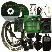
Development and Evaluation Tools 1.3.1 RCM4300 Development Kit The RCM4300 Development Kit contains the hardware essentials you will need to use the RCM4300 module. The items in the Development Kit and their use are as follows. • RCM4300 module. ...
Page 10
... Encryption Standard (AES), and other select libraries. In addition to the Web-based technical support included at no extra charge, a one-year telephone-based technical support module is also available for purchase. Visit our Web site at contact your Rabbit Semiconductor sales representative or authorized distributor for further information. 1.3.3 Online Documentation The online documentation is installed along with Dynamic C, and an icon for the docu- mentation menu is placed on the workstation’ ...
Page 11
... Install Dynamic C To develop and debug programs for the RCM4300 series of modules (and for all other Rabbit Semiconductor hardware), you must install and use Dynamic C. If you have not yet installed Dynamic C version 10.21 (or a later version now by inserting the Dynamic C CD from the Development Kit in your PC’s CD-ROM drive. If autorun is enabled, the CD installation will begin automatically ...
Page 12
Hardware Connections There are four steps to connecting the Prototyping Board for use with Dynamic C and the sample programs: 1. Prepare the Prototyping Board for Development. 2. Attach the RCM4300 module to the Prototyping Board. 3. Connect the ...
Page 13
Step 2 — Attach Module to Prototyping Board Turn the RCM4300 module so that the mounting holes line up with the corresponding holes on the Prototyping Board. Insert the metal standoffs as shown in Figure 3, secure them from ...
Page 14
Step 3 — Connect Programming Cable The programming cable connects the module to the PC running Dynamic C to download programs and to monitor the module during debugging. Connect the 10-pin connector of the programming cable labeled the RCM4300 ...
Page 15
Step 4 — Connect Power Once all the other connections have been made, you can connect power to the Prototyping Board. First, prepare the AC adapter for the country where it will be used by selecting the plug. The ...
Page 16
Run a Sample Program Once the RCM4300 is connected as described in the preceding pages, start Dynamic C by double-clicking on the Dynamic C icon on your desktop or in your Code and BIOS in RAM on the “Compiler” ...
Page 17
... If there are any problems at this point: • Use the Dynamic C Help menu to get further assistance with Dynamic C. • Check the Rabbit Semiconductor Technical Bulletin Board and forums at www.rabbit.com/support/bb/ • Use the Technical Support e-mail form at www.rabbit.com/support/. RabbitCore RCM4300 User’s Manual dialog on the “ ...
Page 18
... R To develop and debug programs for the RCM4300 (and for all other Rabbit Semiconductor hardware), you must install and use Dynamic C. This chapter provides a tour of its major features with respect to the RCM4300. 3.1 Introduction To help familiarize you with the RCM4300 modules, Dynamic C includes several sample programs. Loading, executing and studying these programs will give you a solid hands-on overview of the RCM4300’ ...
Page 19
Sample Programs Of the many sample programs included with Dynamic C, several are specific to the RCM4300 modules. These programs will be found in the —Demonstrates use of the digital outputs by having you turn LEDs • CONTROLLED.C DS2 ...
Page 20
TOGGLESWITCH.C using the press-and-release method of debouncing. LEDs DS2 and DS3 on the Proto- typing Board are turned on and off when you press switches S2 and S3. S2 and ...
Page 21
Serial Communication The following sample programs are found in the —This program demonstrates how to configure Serial Port C for • FLOWCONTROL.C CTS/RTS flow control with serial data coming from Serial Port D (TxD) at 115,200 bps. The serial ...
Page 22
RS-232 serial • SIMPLE3WIRE.C communication. Lower case characters are sent on TxC, and are received by RxD. The received characters are converted to upper case and are sent out on TxD, are received on RxC, and ...
Page 23
IOCONFIG_SWITCHECHO.C which then transmits and then receives an ASCII string when switch S2 is pressed. The echoed serial data are displayed in the Dynamic C Note that the I/O lines that carry the Serial Port E signals are not ...
Page 24
A/D Converter Inputs (RCM4300 only) The following sample programs are found in the AD_CAL_ALL.C —Demonstrates how to recalibrate all the single-ended analog input • channels with one gain using two known voltages to generate the calibration constants for each ...
Page 25
LN7 to calculate temperature • THERMISTOR.C for display to the Dynamic C thermistor is the one included in the Development Kit whose values for beta, series resistance, and resistance at standard temperature are given ...
Page 26
Baud rate 19,200 bps, 8 bits, no parity, 1 stop bit • Enable • Feed options — Follow the remaining steps carefully in Tera Term to avoid overwriting previously saved calibration data when using same the file name. • ...
Page 27
Real-Time Clock If you plan to use the real-time clock functionality in your application, you will need to set the real-time clock. Set the real-time clock using the SETRTCKB.C sample program from the Dynamic C SAMPLES\RTCLOCK folder, using the ...
Page 28
Chapter 4 describes the hardware components and principal hardware subsystems of the RCM4300. Appendix A, “RCM4300 Specifica- tions,” provides complete physical and electrical specifications. Figure 5 shows the Rabbit-based subsystems designed into the RCM4300. 32 kHz Ethernet osc Fast SRAM ...
Page 29
RCM4300 Digital Inputs and Outputs Figure 6 shows the RCM4300 pinouts for header J4. standard 2 × 25 IDC header with a nominal 1.27 mm pitch. Headers RabbitCore RCM4300 User’s Manual Figure 6. RCM4300 Pinout 29 ...
Page 30
Figure 7 shows the use of the Rabbit 4000 microprocessor ports in the RCM4300 modules. Figure 7. Use of Rabbit 4000 Ports The ports on the Rabbit 4000 microprocessor used in the RCM4300 are configurable, and so the factory defaults ...
Page 31
Table 2. RCM4300 Pinout Configurations Pin Pin Name Default Use 1 +3.3 V_IN 2 GND 3 /RES_OUT Reset output 4 /IORD Output 5 /IOWR Output 6 /RESET_IN Input 7 VBAT_EXT Battery input 8–15 PA[0:7] Input/Output 16 PB0 Input/Output 17 PB1 ...
Page 32
Table 2. RCM4300 Pinout Configurations (continued) Pin Pin Name Default Use 24 PC0 Input/Output 25 PC1 Input/Output 26 PC2 Input/Output 27 PC3 Input/Output 28 PC4 Input/Output 29 PC5 Input/Output 30 PC6 Input/Output 31 PC7 Input/Output 32 PE0 Input/Output RabbitCore RCM4300 ...
Page 33
Table 2. RCM4300 Pinout Configurations (continued) Pin Pin Name Default Use 33 PE1 Input/Output 34 /PE2_ENET_EN Input 35 PE3 Input/Output 36 PE4 Input/Output 37 PE5/SMODE0 Input/Output 38 PE6/SMODE1 Input/Output 39 PE7/STATUS Input/Output 40–47 LN[0:7] Analog Input RabbitCore RCM4300 User’s Manual ...
Page 34
Table 2. RCM4300 Pinout Configurations (continued) Pin Pin Name Default Use 40 PD0 Input/Output 41 PD1 Input/Output 42 PD2 Input/Output 43 PD3 Input/Output 44 PD4 Input/Output 45 PD5 Input/Output RabbitCore RCM4300 User’s Manual Alternate Use I/O Strobe I0 Timer C0 ...
Page 35
Table 2. RCM4300 Pinout Configurations (continued) Pin Pin Name Default Use 46 PD6 Input/Output 47 PD7 Input/Output 48 CONVERT Digital Input Analog reference 49 VREF voltage 50 GND Ground 4.1.1 Memory I/O Interface The Rabbit 4000 address lines (A0–A19) and ...
Page 36
Serial Communication The RCM4300 module does not have any serial driver or receiver chips directly on the board. However, a serial interface may be incorporated on the board the RCM4300 is mounted on. For example, the Prototyping Board has ...
Page 37
Table 3 summarizes the possible parallel port pins for the serial ports and their clocks. Remember that the Parallel Port D pins are available only on the RCM4310. Table 3. Rabbit 4000 Serial Port and Clock Pins TXA PC6, PC7, ...
Page 38
Programming Port The RCM4300 is programmed via the 10-pin header labeled J1. The programming port uses the Rabbit 4000’s Serial Port A for communication. Dynamic C uses the programming port to download and debug programs. Serial Port A is ...
Page 39
Programming Cable The programming cable is used to connect the programming port of the RCM4300 serial COM port. The programming cable converts the RS-232 voltage levels used by the PC serial port to the CMOS voltage ...
Page 40
A program “runs” in either mode, but can only be downloaded and debugged when the RCM4300 is in the Program Mode. Refer to the Rabbit 4000 Microprocessor User’s Manual gramming port. 4.3.2 Standalone Operation of the RCM4300 Once the RCM4300 ...
Page 41
A/D Converter (RCM4300 only) The RCM4300 has an onboard ADS7870 A/D converter whose scaling and filtering are done via the motherboard on which the RCM4300 module is mounted. The A/D converter multiplexes converted signals from eight single-ended or four ...
Page 42
If a device such as a battery is connected across two channels for a differential measurement, and it is not referenced to analog ground, then the current from the device will flow through both sets of attenuator resistors without flowing ...
Page 43
A/D Converter Power Supply The analog section is isolated from digital noise generated by other components by way of a low-pass filter composed of C17, L3, and C28 on the RCM4300 as shown in Figure 13. The +V analog ...
Page 44
Other Hardware 4.5.1 Clock Doubler The RCM4300 takes advantage of the Rabbit 4000 microprocessor’s internal clock doubler. A built-in clock doubler allows half-frequency crystals to be used to reduce radiated emissions. The 58.98 MHz frequency specified for the RCM4300 ...
Page 45
Memory 4.6.1 SRAM All RCM4300 modules have 512K of battery-backed data SRAM installed at U10, and the RCM4300 model has 512K of fast SRAM installed at U12. 4.6.2 Flash Memory All RCM4300 modules also have up to 2MB of ...
Page 46
... Figure 14. Insertion/Removal of microSD Card Rabbit Semiconductor recommends that you use the microSD™ Card holder at header J3 only for the microSD™ Card since other devices are not supported. Be careful to remove and insert the card as shown, and be careful not to insert any foreign objects, which may short out the contacts and lead to the destruction of your card possible to hot-swap microSD™ ...
Page 47
Dynamic integrated development system for writing embedded software. It runs on an IBM-compatible PC and is designed for use with single-board computers and other devices based on the Rabbit microprocessor. Chapter 5 describes the libraries and function ...
Page 48
Dynamic C has a number of standard features. • Full-feature source and/or assembly-level debugger, no in-circuit emulator required. • Royalty-free TCP/IP stack with source code and most common protocols. • Hundreds of functions in source-code libraries and sample programs: ...
Page 49
... For more information, see the Dynamic C Function Reference Manual and Rabbit Semiconductor’s Technical Note TN213, Rabbit Serial Port Software. RabbitCore RCM4300 User’s Manual ...
Page 50
Serial Flash Memory Use The RCM4300 module has a serial flash memory that contains the user block and stores the application program. Two function calls are provided to work with the serial boot flash. These function calls are in ...
Page 51
Src, unsigned len); DESCRIPTION Writes len bytes (up to 64K) to physical address flashDst from Src. Keep calling sbfWriteFlash() until it returns zeroa or a negative error code. A positive return value indicates that the ...
Page 52
User Block Certain function calls involve reading and storing calibration constants from/to the simulated EEPROM in flash memory located at the top 2K of the reserved user block memory area (3800–39FF). This leaves the address range 0–37FF in the ...
Page 53
... CLONECONFIG.LIB library. See Rabbit Semiconductor’s Technical Note TN207, Rabbit Cloning Board, for addi- tional information on Rabbit Semiconductor’s cloning board and how cloning is done. 5.2.7 microSD™ Card Drivers The Dynamic C LIB\Rabbit4000\SDflash\SDFLASH.LIB to microSD™ ...
Page 54
Prototyping Board Function Calls The functions described in this section are for use with the Prototyping Board features. The source code is in the Dynamic C library if you need to modify it for your own board design. There ...
Page 55
Alerts These function calls can be found in the Dynamic C library. RCM4xxx.LIB void timedAlert(unsigned long timeout); DESCRIPTION Polls the real-time clock until a timeout occurs. The RCM4400W will low-power mode during this time. Once the ...
Page 56
Analog Inputs (RCM4300 only) The function calls used with the Prototyping Board features and the A/D converter on the RCM4300 model are in the Dynamic C library. Dynamic C v. 10.07 or later is required to use the A/D ...
Page 57
PARAMETERS instructionbyte the instruction byte that will initiate a read or write operation bits on the designated register address. For example, checkid = anaInConfig(0x5F, 0, 9600); the command data that configure the registers addressed ...
Page 58
DESCRIPTION Reads the voltage of an analog input channel by serial-clocking an 8-bit command to the A/D converter by its Direct Mode method. This function assumes that Mode1 (most significant byte first) and the A/D converter ...
Page 59
Differential Input Channel Code Lines 0 +AIN0 -AIN1 1 +AIN2 -AIN3 2 +AIN4 -AIN5 † +AIN6 -AIN7 3 4 -AIN0 +AIN1 5 -AIN2 +AIN3 6 -AIN4 +AIN5 ‡ -AIN6 +AIN7 7 * Negative input is ground. † Not ...
Page 60
DESCRIPTION Reads the value of an analog input channel using the Direct Mode method of addressing the A/D converter. Note that it takes about 1 second to ensure an internal capacitor on ...
Page 61
RETURN VALUE A value corresponding to the voltage on the analog input channel: 0–2047 for single-ended conversions. -2048–2047 for differential conversions. ADSPIBUSY (-4094) if the A/D converter is locked out or if the SPI port is in use (if more ...
Page 62
DESCRIPTION Calibrates the response of the desired A/D converter channel as a linear function using the two conversion points provided. Four values are calculated and ...
Page 63
Prototyping Board): gaincode Gain Code the first A/D converter channel raw count value (0–2047) value1 the voltage or current corresponding ...
Page 64
DESCRIPTION Reads the state of a single-ended analog input channel and uses the previously set calibration constants to convert it to volts. PARAMETERS the channel number ( corresponding to LN0 to ...
Page 65
RETURN VALUE A voltage value corresponding to the voltage on the analog input channel. ADSPIBUSY (-4094) if the A/D converter is locked out or if the SPI port is in use (if more than _SPI_MAXTIME milliseconds elapse since ...
Page 66
DESCRIPTION Reads the state of differential analog input channels and uses the previously set calibra- tion constants to convert it to volts. PARAMETERS the channel number ( corresponding to LN0 to ...
Page 67
RETURN VALUE A voltage value corresponding to the voltage differential on the analog input channel. ADSPIBUSY (-4094) if the A/D converter is locked out or if the SPI port is in use (if more than _SPI_MAXTIME milliseconds elapse ...
Page 68
DESCRIPTION Reads the state of an analog input channel and uses the previously set calibration con- stants to convert it to current. PARAMETERS the channel number ( corresponding to LN0 to LN7. channel RETURN ...
Page 69
DESCRIPTION Reads the calibration constants, gain, and offset for an input based on their designated position in the flash memory, and places them into global tables _adcCalibS, _adc- CalibD, ...
Page 70
The gaincode parameter is ignored when gaincode channel is ALLCHAN. Gain Code Applies to Prototyping Board. RETURN VALUE 0 if successful. -1 ...
Page 71
DESCRIPTION Writes the calibration constants, gain, and offset for an input based from global tables _adcCalibS, _adcCalibD, and _adcCalibM to designated positions in the flash memory. Depending on the flash size, ...
Page 72
The gaincode parameter is ignored when gaincode channel is ALLCHAN. Gain Code Applies to Prototyping Board. RETURN VALUE 0 if successful -1 ...
Page 73
... Add-On Modules Dynamic C installations are designed for use with the board they are included with, and are included at no charge as part of our low-cost kits. Rabbit Semiconductor offers for purchase add-on Dynamic C modules including the popular C/OS-II real-time operating system, as well as PPP, Advanced Encryption Standard (AES), FAT file system, Rabbit- Web, and other select libraries ...
Page 74
... Figure 15 shows how to identify the two Ethernet cables based on the wires in the trans- parent RJ-45 connectors. Figure 15. How to Identify Straight-Through and Crossover Ethernet Cables Ethernet cables and a 10Base-T Ethernet hub are available from Rabbit Semiconductor in a TCP/IP tool kit. More information is available at www.rabbit.com. Now you should be able to make your connections. ...
Page 75
Connect the AC adapter and the serial programming cable as shown in Chapter 2, “Get- ting Started.” 2. Ethernet Connections There are four options for connecting the RCM4300 module to a network for develop- ment and runtime purposes. The ...
Page 76
TCP/IP Primer on IP Addresses Obtaining IP addresses to interact over an existing, operating, network can involve a num- ber of complications, and must usually be done with cooperation from your ISP and/or network systems administrator. For this reason, ...
Page 77
Firewall T1 in Adapter Server Ethernet Typical Corporate Network If your system administrator can give you an Ethernet cable along with its IP address, the netmask and the gateway address, then you may be able to run the sample programs ...
Page 78
IP Addresses Explained IP (Internet Protocol) addresses are expressed as 4 decimal numbers separated by periods, for example: 216.103.126.155 10.1.1.6 Each decimal number must be between 0 and 255. The total IP address is a 32-bit number consisting of ...
Page 79
How IP Addresses are Used The actual hardware connection via an Ethernet uses Ethernet adapter addresses (also called MAC addresses). These are 48-bit addresses and are unique for every Ethernet adapter manufactured. In order to send a packet to ...
Page 80
Dynamically Assigned Internet Addresses In many instances, devices on a network do not have fixed IP addresses. This is the case when, for example, you are assigned an IP address dynamically by your dial-up Internet service provider (ISP) or ...
Page 81
Placing Your Device on the Network In many corporate settings, users are isolated from the Internet by a firewall and/or a proxy server. These devices attempt to secure the company from unauthorized network traffic, and usually work by disallowing ...
Page 82
Running TCP/IP Sample Programs We have provided a number of sample programs demonstrating various uses of TCP/IP for networking embedded systems. These programs require you to connect your PC and the RCM4300 module together on the same network. This ...
Page 83
How to Set IP Addresses in the Sample Programs With the introduction of Dynamic C 7.30 we have taken steps to make it easier to run many of our sample programs. You will see a Dynamic C to select ...
Page 84
... Half-Duplex” “Auto-Negotiation” connection on the “Advanced” tab. NOTE: Your network interface card will likely have a different name. 3. Now select the IP Address click on “Properties” to assign an IP address to your computer (this will disable “obtain an IP address automatically”): IP Address : 10.10.6.101 Netmask : 255.255.255.0 Default gateway : 10.10.6.1 4. Click <OK> or < ...
Page 85
... Start > Run and typing the entry ping 10.10.6.101 The ping routine will ping the module four times and write a summary message on the screen describing the operation. 6.6 Running Additional Sample Programs With Direct Connect The following sample programs are in the Dynamic C folder. — ...
Page 86
... Use the Dynamic C Help menu to get further assistance with Dynamic C. • Check the Rabbit Semiconductor Technical Bulletin Board and forums at www.rabbit.com/support/bb/ • Use the Technical Support e-mail form at www.rabbit.com/support/. If the sample programs ran fine, you are now ready to go on. ...
Page 87
A A. RCM4300 S PPENDIX Appendix A provides the specifications for the RCM4300, and describes the conformal coating. RabbitCore RCM4300 User’s Manual PECIFICATIONS 87 ...
Page 88
A.1 Electrical and Mechanical Characteristics Figure A-1 shows the mechanical dimensions for the RCM4300. Figure A-1. RCM4300 Dimensions NOTE: All measurements are in inches followed by millimeters enclosed in parentheses. All dimensions have a manufacturing tolerance of ±0.01" (0.25 mm). ...
Page 89
It is recommended that you allow for an “exclusion zone” of 0.04" (1 mm) around the RCM4300 in all directions when the RCM4300 is incorporated into an assembly that includes other printed circuit boards. An “exclusion zone” of 0.08" (2 ...
Page 90
Table A-1 lists the electrical, mechanical, and environmental specifications for the RCM4300. Table A-1. RabbitCore RCM4300 Specifications Parameter Microprocessor EMI Reduction Ethernet Port Data SRAM Program Execution Fast SRAM Serial Flash Memory (program) Memory (data storage) LED Indicators Backup Battery ...
Page 91
Table A-1. RabbitCore RCM4300 Specifications (continued) Parameter Serial Ports Serial Rate Slave Interface Real-Time Clock Timers Watchdog/Supervisor Pulse-Width Modulators Input Capture Quadrature Decoder Power (pins unloaded) Operating Temperature Humidity Connectors Board Size RabbitCore RCM4300 User’s Manual RCM4300 5 shared high-speed, ...
Page 92
A.1.1 A/D Converter Table A-2 shows some of the important A/D converter specifications. For more details, refer to the ADS7870 data sheet. Table A-2. A/D Converter Specifications Parameter Analog Input Characteristics Input Capacitance Input Impedance Common-Mode Differential Mode Static Accuracy ...
Page 93
A.1.2 Headers The RCM4300 uses headers at J1 and J4 for physical connection to other boards × 25 SMT header with a 1.27 mm pin spacing. J1, the programming port × 5 header ...
Page 94
A.2 Rabbit 4000 DC Characteristics Table A-3. Rabbit 4000 Absolute Maximum Ratings Symbol T Operating Temperature A T Storage Temperature S V Maximum Input Voltage IH VDD Maximum Operating Voltage IO Stresses beyond those listed in Table A-3 may cause ...
Page 95
A.3 I/O Buffer Sourcing and Sinking Limit Unless otherwise specified, the Rabbit I/O buffers are capable of sourcing and sinking current per pin at full AC switching speed. Full AC switching assumes a 29.4 MHz CPU clock ...
Page 96
Figure A-4 shows a typical timing diagram for the Rabbit 4000 microprocessor external I/O read and write cycles. Figure A-4. I/O Read and Write Cycles—No Extra Wait States NOTE: /IOCSx can be programmed to be active low (default) or active ...
Page 97
... The maxi- mum shortening for a pair of clocks combined is shown in the table. Rabbit Semiconductor’s Technical Note TN227, Interfacing External I/O with Rabbit 2000/3000 Designs, contains suggestions for interfacing I/O devices to the Rabbit 3000 and Rabbit 4000 microprocessors. RabbitCore RCM4300 User’ ...
Page 98
A.5 Jumper Configurations Figure A-5 shows the jumper locations used to configure the various RCM4300 options. The black square indicates pin 1. Figure A-5. Location of RCM4300 Configurable Positions Table A-8 lists the configuration options. Table A-8. RCM4300 Jumper Configurations ...
Page 99
Table A-8. RCM4300 Jumper Configurations Header Description JP6 LN2 or PD2 on J4 pin 42 JP7 LN3 or PD3 on J4 pin 43 JP8 LN4 or PD4 on J4 pin 44 JP9 LN6 or PD6 on J4 pin 46 JP10 ...
Page 100
... Any components in the conformally coated area may be replaced using standard soldering procedures for surface-mounted components. A new conformal coating should then be applied to offer continuing protection against the effects of moisture and contaminants. NOTE: For more information on conformal coatings, refer to Rabbit Semiconductor’s Technical Note 303, Conformal Coatings. RabbitCore RCM4300 User’s Manual ...
Page 101
... RCM4300 and to build prototypes of your own circuits. The Prototyping Board has power-supply connections and also provides some basic I/O peripherals (RS-232, LEDs, and switches), as well as a prototyping area for more advanced hardware development. RabbitCore RCM4300 User’s Manual B. P ROTOTYPING B OARD 101 ...
Page 102
B.1 Introduction The Prototyping Board included in the Development Kit makes it easy to connect an RCM4300 module to a power supply and a PC workstation for development. It also pro- vides some basic I/O peripherals (RS-232, LEDs, and switches), ...
Page 103
B.1.1 Prototyping Board Features —A a 3-pin header is provided for connection to the power supply. • Power Connection Note that the 3-pin header is symmetrical, with both outer pins connected to ground and the center pin connected to the ...
Page 104
RS-232 serial ports are available on the Prototyp- • RS-232 ing Board at header J4. A 10-pin 0.1" pitch header strip installed at J4 allows you to connect a ribbon cable that leads to a ...
Page 105
B.2 Mechanical Dimensions and Layout Figure B-2 shows the mechanical dimensions and layout for the Prototyping Board. Figure B-2. Prototyping Board Dimensions RabbitCore RCM4300 User’s Manual 105 ...
Page 106
Table B-1 lists the electrical, mechanical, and environmental specifications for the Proto- typing Board. Table B-1. Prototyping Board Specifications Parameter Board Size Operating Temperature Humidity Input Voltage Maximum Current Draw (including user-added circuits) Prototyping Area Connectors B.3 Power Supply The ...
Page 107
B.4 Using the Prototyping Board The Prototyping Board is actually both a demonstration board and a prototyping board demonstration board, it can be used to demonstrate the functionality of the RCM4300 right out of the box without any ...
Page 108
All signals from the RCM4300 module are available on header J2 of the Prototyping Board. The remaining ports on the Rabbit 4000 microprocessor are used for RS-232 serial communication. Table B-2 lists the signals on header J2 and explains how ...
Page 109
B.4.1 Adding Other Components There are pads for 28-pin TSSOP devices, 16-pin SOIC devices, and 6-pin SOT devices that can be used for surface-mount prototyping with these devices. There are also pads that can be used for SMT resistors and ...
Page 110
B.4.3 Analog Features (RCM4300 only) The Prototyping Board has typical support circuitry installed to complement the ADS7870 A/D converter on the RCM4300 model (the A/D converter is not available on the RCM4210 model). B.4.3.1 A/D Converter Inputs Figure B-6 shows ...
Page 111
... Adjacent input channels are paired; moving the jumper changes both of the paired channels (LN4_IN–LN5_IN), and moving the jumper on JP24 changes LN0_IN– LN1_IN and LN2_IN–LN3_IN. At the present time Rabbit Semiconductor does not offer the software drivers to work with single-ended negative voltages, but the differential mode described below may be used to measure negative voltages ...
Page 112
B.4.3.2 Thermistor Input Analog input LN7_IN on the Prototyping Board was designed specifically for use with a thermistor at JP25 in conjunction with the strates how to use the analog input to measure temperature, which will be displayed in the ...
Page 113
B.4.4 Serial Communication The Prototyping Board allows you to access the serial ports from the RCM4300 module. Table B-5 summarizes the configuration options. Note that Serial Ports F can be used only when the RCM4310 is installed on the Prototyping ...
Page 114
B.4.4.1 RS-232 RS-232 serial communication on header J4 on both Prototyping Boards is supported by an RS-232 transceiver installed at U3. This transceiver provides the voltage output, slew rate, and input voltage immunity required to meet the RS-232 serial communication ...
Page 115
B.5 Prototyping Board Jumper Configurations Figure B-8 shows the header locations used to configure the various Prototyping Board options via jumpers. Figure B-8. Location of Configurable Jumpers on Prototyping Board Table B-6 lists the configuration options using either jumpers or ...
Page 116
Table B-6. RCM4300 Prototyping Board Jumper Configurations (continued) Header Description JP5 PC1/RxD/Switch S2 JP6 JP7 PC2/TxC/LED DS3 JP8 JP9 PC3/RxC/Switch S3 JP10 JP11 LN0 buffer/filter to RCM4300 JP12 PB2/LED DS2 JP13 LN1 buffer/filter to RCM4300 JP14 PB3/LED DS3 JP15 LN2 ...
Page 117
Table B-6. RCM4300 Prototyping Board Jumper Configurations (continued) Header Description JP23 LN4_IN–LN6_IN JP24 LN0_IN–LN3_IN JP25 Thermistor Location NOTE: Jumper connections JP3–JP10, JP12, JP14, JP16, JP18, JP23, and JP24 are made using 0 surface-mounted resistors. Jumper connections JP11, JP13, JP15, ...
Page 118
A PPENDIX Appendix C provides information on the current requirements of the RCM4300, and includes some background on the chip select circuit used in power management. C.1 Power Supplies The RCM4300 requires a regulated 3.0 V – 3 ...
Page 119
... NOTE: Remember to cycle the main power off/on any time the RCM4300 is removed from the Prototyping Board or motherboard since that is where the backup battery would be located. Rabbit Semiconductor’s Technical Note TN235, External 32.768 kHz Oscillator Circuits, provides additional information about the current draw by the real-time clock oscillator circuit. ...
Page 120
C.1.3 Reset Generator The RCM4300 uses a reset generator to reset the Rabbit 4000 microprocessor when the volt- age drops below the voltage necessary for reliable operation. The reset occurs between 2.85 V and 3.00 V, typically 2.93 V. Since ...
Page 121
A A/D converter access via Prototyping Board 110 function calls anaIn .............................. 60 anaInCalib ..................... 62 anaInConfig ................... 56 anaInDiff ....................... 66 anaInDriver ................... 58 anaInEERd .................... 69 anaInEEWr .................... 71 anaInmAmps ................. 68 anaInVolts ..................... 64 inputs differential measurements ...
Page 122
JP1 (LN0 buffer/filter to RCM4300) ................ 116 JP12 (PB2/LED DS2) . 116 JP13 (LN1 buffer/filter to RCM4300) ................ 116 JP14 (PB3/LED DS3) . 116 JP15 (LN2 buffer/filter to RCM4300) ................ 116 JP16 (PB4/Switch S2) . 116 JP17 (LN3 buffer/filter to ...
Page 123
RS-232 ........................ 114 software PACKET.LIB ................ 49 RS232.LIB .................... 49 serial flash memory function calls ..................... 50 sbfRead .......................... 50 sbfWriteFlash ................ 51 software BOOTDEV_SFLASH.LIB 50 serial ports ............................. 36 Ethernet port ..................... 37 programming port ............. 38 Serial Port ...
Page 124
RCM4300 Schematic www.rabbit.com/documentation/schemat/090-0229.pdf 090-0230 Prototyping Board Schematic www.rabbit.com/documentation/schemat/090-0230.pdf 090-0252 USB Programming Cable Schematic www.rabbit.com/documentation/schemat/090-0252.pdf You may use the URL information provided above to access the latest schematics directly. RabbitCore RCM4300 User’s Manual S CHEMATICS 125 ...