EDB9315A-Z Cirrus Logic Inc, EDB9315A-Z Datasheet - Page 13
EDB9315A-Z
Manufacturer Part Number
EDB9315A-Z
Description
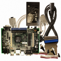
KIT DEVELOPMENT EP9315 ARM9
Manufacturer
Cirrus Logic Inc
Type
MCUr
Specifications of EDB9315A-Z
Contents
Development Board, Software, Schematics, Gerbers, Power Supply, Cable and Documentation
Silicon Manufacturer
Cirrus Logic
Core Architecture
ARM
Core Sub-architecture
ARM9
Features
Serial EEPROM Interface, 10/100 Mbps Ethernet, External Battery Backed RTC
Silicon Family Name
ARM
Silicon Core Number
EP9315
Rohs Compliant
Yes
Lead Free Status / RoHS Status
Lead free / RoHS Compliant
For Use With/related Products
EP9312, EP9315
Lead Free Status / RoHS Status
Lead free / RoHS Compliant, Lead free / RoHS Compliant
Other names
598-1144
EDB9315A
EDB9315A


EDB9315A
Technical Reference Manual
Page 9
The two connectors provide a daughter card interface for making custom circuits. J4 is the Memory
Expansion connector and J5 is the Peripheral Expansion connector.
The entire memory bus is connected to J5. It is recommended that the bus signals be buffered if adding
additional memory. However if a CPLD or FPGA is attached there is no reason to buffer. Use proper
engineering practices when using the high-speed memory bus with daughter cards.
The Peripheral Expansion bus has the signals for features not implemented on the EDB9315A board and
for commonly used signals.
Page 10
The IDE interface is connected from the EP9315 device to the IDE connector, JP5, through series
termination resistors. These pins are 5V tolerant.
A hard disk drive (HDD) and/or CD-ROM can be connected to the board with the IDE cable provided.
Simply plug the blue end of the IDE cable into the blue IDE connector, JP5. Power for the drive(s) is
provided by plugging the IDE power cable (included) into the IDE power connector, JP4.
If using a notebook HDD, please use the included 3.5”-to-2.5” IDE power adapter.
Page 11
Two video interfaces are provided. The main video interface is VGA. An LCD interface is also provided
however there is no LCD screen included with the development kit. The LCD interface is pin compatible
with previous Cirrus Logic ARM9 development boards. A 4-wire touch screen interface is also included
and is pin compatible with previous Cirrus Logic ARM9 development boards.
Page 12
An external USB 2.0 High-speed Peripheral device is provided. The USB device allows a Host to see the
board as a Mass Storage device. The USB interface chip is connected to the lower 16-bits of the
memory bus.
Page 13
Audio is supported by a Cirrus Logic CS4271 device. Two-channel audio out and line-level audio in is
2
supported. The audio device communicates to the EP9315 through the I
S interface and audio clocks
are generated by the EP9315. The audio in is line level, it is not a microphone-level input. Like the serial
EEPROM, the CS4271 is controlled by the SPI frame signal and EGPIO6. EGPIO6 must be low in order
to communicate to the CS4271 device. As mentioned before, only one SPI™ device can be enabled at a
time.
©
DS638DB3
Copyright 2006 Cirrus Logic, Inc.
13
Related parts for EDB9315A-Z
Image
Part Number
Description
Manufacturer
Datasheet
Request
R

Part Number:
Description:
Microprocessor Development Tool
Manufacturer:
Cirrus Logic Inc
Datasheet:

Part Number:
Description:
Development Kit
Manufacturer:
Cirrus Logic Inc
Datasheet:
Part Number:
Description:
Development Kit
Manufacturer:
Cirrus Logic Inc
Datasheet:


Part Number:
Description:
High-efficiency PFC + Fluorescent Lamp Driver Reference Design
Manufacturer:
Cirrus Logic Inc
Datasheet:
Part Number:
Description:
Development Kit
Manufacturer:
Cirrus Logic Inc
Datasheet:
Part Number:
Description:
Development Kit
Manufacturer:
Cirrus Logic Inc
Datasheet:

Part Number:
Description:
Development Kit
Manufacturer:
Cirrus Logic Inc
Datasheet:
Part Number:
Description:
Development Kit
Manufacturer:
Cirrus Logic Inc
Datasheet:
Part Number:
Description:
Development Kit
Manufacturer:
Cirrus Logic Inc
Datasheet:

Part Number:
Description:
EVALUATION BOARD FOR CS8427
Manufacturer:
Cirrus Logic Inc
Datasheet:

Part Number:
Description:
BOARD EVAL FOR CS8416 RCVR
Manufacturer:
Cirrus Logic Inc
Datasheet:

Part Number:
Description:
EVALUATION BOARD FOR CS8420
Manufacturer:
Cirrus Logic Inc
Datasheet:

Part Number:
Description:
KIT DEVELOPMENT EP9302 ARM9
Manufacturer:
Cirrus Logic Inc
Datasheet:

Part Number:
Description:
KIT DEVELOPMENT EP9307 ARM9
Manufacturer:
Cirrus Logic Inc
Datasheet: