101-0552 Rabbit Semiconductor, 101-0552 Datasheet - Page 17
101-0552
Manufacturer Part Number
101-0552
Description
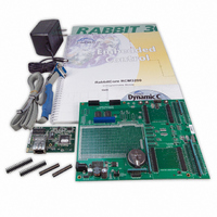
KIT DEV RABBITCORE/RCM3200
Manufacturer
Rabbit Semiconductor
Series
RabbitCore 3000r
Type
MPU Moduler
Datasheet
1.20-101-1217.pdf
(138 pages)
Specifications of 101-0552
Rohs Status
RoHS non-compliant
Contents
RabbitCore Module, Dev. Board, AC Adapter, Cable and Dynamic C® CD-Rom
For Use With/related Products
RCM3200
Lead Free Status / Rohs Status
Lead free / RoHS Compliant
Other names
316-1023


2.2.1 Step 1 — Attach Module to Prototyping Board
Turn the RCM3200 series module so that the Ethernet jack extends off the Prototyping
Board, as shown in Figure 2 below. Align the pins from the headers on the bottom side of
the module into header sockets RCM2JA and RCM2JB on the Prototyping Board (these
sockets were labeled J12 and J13 on earlier versions of the Prototyping Board).
Although you can install a single module into either the
on the Prototyping Board, all the Prototyping Board features (switches, LEDs, serial port
drivers, etc.) are connected to the
MASTER
Press the module’s pins firmly into the Prototyping Board header sockets—press down in
the area above the header pins using your thumbs or fingers over the connectors as shown
in Figure 2. Do not press down on the middle of the RCM3200 series module to avoid
flexing the module, which could damage the module or the components on the module.
Should you need to remove the RCM3200 module, grasp it with your fingers along the sides
by the connectors and gently work the module up to pull the pins away from the sockets
where they are installed. Do not remove the module by grasping it at the top and bottom.
User’s Manual
NOTE: It is important that you line up the pins from the headers on the bottom side of the
Figure 2. Install the RCM3200 Series Module on the Prototyping Board
RCM3200 module exactly with the corresponding pins of header sockets RCM2JA and
RCM2JB on the Prototyping Board. The header pins may become bent or damaged if
the pin alignment is offset, and the module will not work. Permanent electrical damage
to the module may also result if a misaligned module is powered up.
position.
MASTER
position — install a single module in the
MASTER
or the
SLAVE position
11
Related parts for 101-0552
Image
Part Number
Description
Manufacturer
Datasheet
Request
R

Part Number:
Description:
COMPUTER SNGLBD BL2101 A/D 0-10V
Manufacturer:
Rabbit Semiconductor
Part Number:
Description:
CARD D/A 0-10V SR9400 SMARTSTAR
Manufacturer:
Rabbit Semiconductor
Datasheet:
Part Number:
Description:
CARD A/D 0-10V SR9300 SMARTSTAR
Manufacturer:
Rabbit Semiconductor
Datasheet:

Part Number:
Description:
WiFi / 802.11 Modules & Development Tools WIRELESS CONTROL APP KIT
Manufacturer:
Rabbit Semiconductor

Part Number:
Description:
KIT DEV RABBITCORE RCM3750
Manufacturer:
Rabbit Semiconductor
Datasheet:
Part Number:
Description:
KIT DEV RABBIT 2000 INT'L
Manufacturer:
Rabbit Semiconductor
Datasheet:
Part Number:
Description:
KIT DEV RABBIT RCM2000 INT'L
Manufacturer:
Rabbit Semiconductor
Datasheet:

Part Number:
Description:
KIT DEVELOPMENT RCM3700 INT'L
Manufacturer:
Rabbit Semiconductor
Datasheet:

Part Number:
Description:
BL4S200 TOOL KIT
Manufacturer:
Rabbit Semiconductor
Datasheet:
Part Number:
Description:
MODULE RABBITCORE RCM3720
Manufacturer:
Rabbit Semiconductor
Datasheet:
Part Number:
Description:
MODULE RABBITCORE RCM3220
Manufacturer:
Rabbit Semiconductor
Datasheet:
Part Number:
Description:
MODULE RABBITCORE RCM3210
Manufacturer:
Rabbit Semiconductor
Datasheet:
Part Number:
Description:
COMPUTER SGL-BOARD OP6600 W/SRAM
Manufacturer:
Rabbit Semiconductor
Datasheet:
Part Number:
Description:
COMPUTER SGL-BD BL2000 SRAM/FLSH
Manufacturer:
Rabbit Semiconductor