Z16F2800100ZCOG Zilog, Z16F2800100ZCOG Datasheet
Z16F2800100ZCOG
Specifications of Z16F2800100ZCOG


Related parts for Z16F2800100ZCOG


Z16F2800100ZCOG Summary of contents
Page 1
... Z16F2800100ZCOG ZNEO™ Series of Microcontrollers Development Kit User Manual UM020203-0606 ZiLOG Worldwide Headquarters • 532 Race Street • San Jose, CA 95126 Telephone: 408.558.8500 • Fax: 408.558.8300 • www.ZiLOG.com ...
Page 2
... Document Disclaimer ZiLOG is a registered trademark of ZiLOG Inc. in the United States and in other countries. All other products and/or service names mentioned herein may be trademarks of the companies with which they are associated. ©2006 by ZiLOG, Inc. All rights reserved. Information in this publication concerning the devices, applications, or technology described is intended to suggest possible uses and may be superseded ...
Page 3
Revision History Each instance in Table 1 reflects a change to this document from its previ- ous revision. To see more detail, click the appropriate link in the table. Table 1. Revision History of this Document Revision Date Level Section ...
Page 4
ZNEO™ Series Development Kit User Manual iv Safeguards The following precautions must be observed when working with the devices described in this document. Always use a grounding strap to prevent damage resulting from Caution: electrostatic discharge (ESD). Safeguards PRELIMINARY UM020203-0606 ...
Page 5
Table of Contents Revision History ...
Page 6
ZNEO™ Series Development Kit User Manual vi Table of Contents UM020203-0606 ...
Page 7
List of Figures Figure 1. Figure 2. Figure 3. UM020203-0606 ZNEO™ Series Development Kit ZNEO™ Series Development Board . . . . . . . . . . . . . . . . . .5 ZNEO Series Development Kit ...
Page 8
ZNEO™ Series Development Kit User Manual viii List of Figures UM020203-0606 ...
Page 9
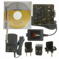
... Introduction The ZNEO™ Series MCU is part of the line of ZiLOG microcontroller products. The ZNEO™ Series MCU Development Kit (Z16F2800100ZCOG) enables users to become familiar with the hardware and software tools available with this product. This kit consists of the 128KB version of the ZNEO™ ...
Page 10
ZNEO™ Series Development Kit User Manual 2 Introduction UM020203-0606 ...
Page 11
Installation Follow the directions in the Quick Start Guide for software installation and setup of the ZNEO™ Series Development kit. UM020203-0606 ZNEO™ Series Development Kit User Manual Installation 3 ...
Page 12
ZNEO™ Series Development Kit User Manual 4 Installation UM020203-0606 ...
Page 13
ZNEO™ Series Development Board Introduction The ZNEO™ Series Development board is a development and prototyp- ing board for the ZNEO™ Series MCU. The board provides customers with a tool to evaluate features of ZNEO™ Series MCU, and to start developing ...
Page 14
... LEDs • RS-232 interface • On-Chip Debugger interface • IrDA transceiver • Electrical and mechanical compatibility with ZiLOG MDS architec- ture • One RESET pushbutton (S1) • Two SPST switches (S2, STOP/RUN and S3, DIRECTION) • 5 VDC power connector • 20 MHz Ceramic Oscillator (Y1) • ...
Page 15
Z8F1285 (128KB FLASH, ZNEO™ MCU 4KB SRAM, 12 channel ADC, 3 channel PWM) 20 MHz XTAL FLASH (1Mx16, CS0) SRAM (256Kx16, CS1) Figure 2. ZNEO Series Development Kit Block Diagram UM020203-0606 ZNEO™ Series Development Kit GPIO External Interface Address and ...
Page 16
ZNEO™ Series Development Kit User Manual 8 ZNEO MEMORY LAYOUT The ZNEO CPU has a unique memory architecture with a unified 24-bit physical address space, which is partitioned into several distinct memory areas. In terms of physical memory spaces, the ...
Page 17
Memory Internal I/O Memory & SFRs External Memory Mapped Peripherals (optional) External Memory at CS2 (optional) Internal RAM External Memory at CS2 (optional) External Memory at CS1 (optional) External Memory at CS0 (optional) Internal Nonvolatile Memory Figure 3. ZNEO Physical ...
Page 18
ZNEO™ Series Development Kit User Manual 10 Each of the internal memory spaces has a distinct purpose. Internal non- volatile memory typically contains executable program code and constant data. ZNEO-CPU-based devices have internal nonvolatile memory start- ing at address Flash ...
Page 19
... Manual and the individual device product specification for more informa- tion. MCU The ZNEO Z16F Series Flash microcontrollers are based on ZiLOG’s advanced ZNEO 16-bit CPU core. The ZNEO Z16F Series MCU family of devices sets a new standard of performance and efficiency with a 24-bit address bus and 16-bit data bus ...
Page 20
ZNEO™ Series Development Kit User Manual 12 – – – • twelve channels 10-bit analog-to-digital converter (ADC) • Operational Amplifier • Analog Comparator • 4-channel DMA controller supports internal or external DMA requests • Two full-duplex 9-bit UARTS ...
Page 21
... For further information on the ZNEO™ family of devices, consult the product specification, P/N PS0220, available for download from www.zilog.com. UART with IrDA Endec The ZNEO Series contains a fully-functional, high-performance UART with Infrared Encoder/Decoder (ENDEC). The Infrared Endec is inte- grated with an on-chip UART (component U13) allowing easy communi- cation between the ZNEO Series and IrDA transceivers ...
Page 22
ZNEO™ Series Development Kit User Manual 14 Jumper Settings Table 1 provides information on the shunt status, functions, and defaults of jumpers on the ZNEO Series development board. Table 1. ZNEO Jumper Settings Jumper J1 J1 J2* J2 J3* J3 ...
Page 23
External Interface Headers JP1, JP2, and JP4 External interface headers JP1, JP2, and JP4 are shown in the schematic on page 21. UM020203-0606 ZNEO™ Series Development Kit User Manual ZNEO™ Series Development Board 15 ...
Page 24
ZNEO™ Series Development Kit User Manual 16 ZNEO™ Series Development Board UM020203-0606 ...
Page 25
Schematic This section includes schematics for the ZNEO™ Series Development Board. UM020203-0606 ZNEO™ Series Development Kit PRELIMINARY User Manual 17 Schematic ...
Page 26
ZNEO™ Series Development Kit User Manual 18 Schematic PRELIMINARY UM020203-0606 ...
Page 27
POWER&COMMUNICATIONS PA0_T0IN PA1_T0OUT PA2_DE0 PA7_SDA PC0_T1IN A1 A1 PA3_CTS0 PA4_RXD0 PA5_TXD0 -RESET TXD1 TXD1 -DIS_232 -DIS_232 RXD1 -DIS_IrDA -DIS_IRDA FAB FAB POWER&COMMUNICATIONS Schematic, ZNEO™ Series MCU Development Board, Page UM020203-0606 MCU MDS INTERFACE D[15:0] PA0 PA0 D[15:0] ...
Page 28
PA0_T0IN 1 PA0/T0IN/OUT/DMA0REQ PD2_PWMH2_ADR22 2 PD2/PWMH2/ADR22 PC2_nSS 3 PC2/SS/CS4 PF6_ADR6 4 PF6/ADR6 -RESET 5 -RESET RESET VCC_33v 6 VDD PF5_ADR5 7 PF5/ADR5 PF4_ADR4 8 PF4/ADR4 PF3_ADR3 9 PF3/ADR3 PE4_DATA4 10 PE4/DATA4 PE3_DATA3 11 PE3/DATA3 GND 12 ...
Page 29
-FLASH_EN ...
Page 30
VCC_5V 1 C45 C45 CON DC CON DC 0.1uF 0.1uF U12 U12 SPX2815AU-3.3 SPX2815AU-3 C49 C49 + + 10uF 10uF C50 C50 0.1uF 0.1uF C -RESET VCC_33V R17 R17 ...