28138 Parallax Inc, 28138 Datasheet
28138
Specifications of 28138


Related parts for 28138


28138 Summary of contents
Page 1
... RS-232 DCE port with MAX232E transceiver 2 ® DS1307 ( real-time-clock with 3v back-up battery (pre-installed) Copyright © Parallax, Inc. Professional Development Board (#28138) Web Site: www.parallax.com Office: (916) 624-8333 Forums: forums.parallax.com Fax: (916) 624-8003 Sales: sales@parallax.com Sales: (888) 512-1024 Technical: support@parallax.com Tech Support: (888) 997-8267 ® ...
Page 2
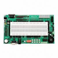
... RJ-11 connector for X-10 or 1-Wire I/O Q) MAX232E RS-232 DCE line driver 2 R) DS1307 I C real-time clock with 3V battery backup S) SX28AC/DP socket T) SX-Key/SX-Blitz programming connection U) Solderless breadboard for connecting external components Copyright © Parallax, Inc. Professional Development Board (#28138) v2.0 9/3/2008 Page ...
Page 3
... The purpose of the VIN terminal is to provide +12 volts (the typical input voltage to the PDB) to external devices like relays, incandescent lamps, and stepper motors that are control via the L293D push-pull driver. Copyright © Parallax, Inc. Professional Development Board (#28138) ® products; is there anything else I’ll need? v2.0 9/3/2008 Page ...
Page 4
... You may download the schematic for the PDB free from our website by typing in the product number (28138) into our search box. Please refer to the PDB schematic for detailed information about each circuit on the board. For additional information on some of the integrated circuits included on the PDB, such as the L293D, DS1307, LM386 or MAX232E, please download the manufacturer’ ...
Page 5
... CAUTION: The SX28AC/DP micro must be removed before installing and using the BS2p40. Having both modules installed at the same time could cause an I/O pin conflict that could lead to damage to one or both of the modules. Copyright © Parallax, Inc. Professional Development Board (#28138) A 24-pin v2.0 9/3/2008 Page ...
Page 6
... LCD data buss (DB0 – DB7) is split, and the E, RW, and RS lines have dual connections as shown in the diagram at right. This configuration allows both 4- and 8-bit LCD applications to be developed. The potentiometer located near X1 is used to adjust LCD display contrast. Copyright © Parallax, Inc. Professional Development Board (#28138 ...
Page 7
... Eight normally-open pushbuttons and eight DIP switches are made available via connectors X9 and X10. The buttons and the switches are wired in an active-low configuration, with an I/O pin protection resistor as shown in the illustration below. Copyright © Parallax, Inc. Professional Development Board (#28138) A 220 series Its push-pull on ...
Page 8
... DCE port on the PDB allows for full flow-control (both transmit and receive). Note that the pin names refer to function, hence X13-RX will connect to the receive pin (e.g., SERIN) of your project. Copyright © Parallax, Inc. Professional Development Board (#28138) 1-Wire I/O v2.0 9/3/2008 Page The ...
Page 9
... SX-Key. For stand-alone testing, remove the SX-Key and install an appropriate 3-pin ceramic resonator into socket Y1. Board Dimensions 9” 5-1/4” ¾” cm) Copyright © Parallax, Inc. Professional Development Board (#28138) Data transfer 2 C protocol which is directly supported by the v2.0 9/3/2008 Page ...
Page 10
... MHz resonator #250-05060 20 MHz resonator #250-02060 4 MHz resonator #250-04050 Copyright © Parallax, Inc. Professional Development Board (#28138) 12 VDC, 1 Amp power supply #750-00007 9 VDC, 300 mA power supply #750-00008 7.5 VDC, 1 Amp power supply #750-00009 ...