STM8L1526-EVAL STMicroelectronics, STM8L1526-EVAL Datasheet - Page 13
STM8L1526-EVAL
Manufacturer Part Number
STM8L1526-EVAL
Description
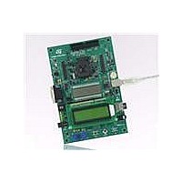
BOARD EVAL FOR STM8L152C6
Manufacturer
STMicroelectronics
Series
STM8L EnergyLiter
Type
MCUr
Specifications of STM8L1526-EVAL
Contents
Board
Processor To Be Evaluated
STM8L15x
Data Bus Width
8 bit
Interface Type
RS-232, USB, SPI, USART
Operating Supply Voltage
5 V
Core Architecture
STM8
Core Sub-architecture
STM8
Silicon Core Number
STM8
Silicon Family Name
STM8L1xx
Silicon Manufacturer
ST Micro
For Use With/related Products
STM8L152C6
Lead Free Status / RoHS Status
Lead free / RoHS Compliant
Other names
497-10590
Available stocks
Company
Part Number
Manufacturer
Quantity
Price
Company:

Part Number:
STM8L1526-EVAL
Manufacturer:
OMRON
Quantity:
30 000


STM8L1526-EVAL
2.8
Motor control
The STM8L1526-EVAL supports three-phase brushless motor control via a 34-pin
connector, CN7, which provides all required control and feedback signals to and from motor
power-driving board. Available signals on this connector include emergency stop, motor
speed, 3 phase motor current, bus voltage, heat sink temperature coming from the motor
driving board and 6 channels of PWM control signal going to the motor driving circuit.
The I/O pins used on the motor control connector, CN7, are multiplexed with some
peripherals on the board. The motor control application can be enabled by setting jumpers
JP3, JP4 and JP8.
Table 8.
Some rework that is required to be done to the board is listed below:
The LCD glass module has to be mounted in the IO position for motor control. Refer to
Section 2.4: LCD glass module
JP4
JP8
JP3
Jumper
Remove 0 ohm resistors, R69, R75,R80,R58,R35,R42,R31,R34,R62,R39,R55 and
R48 (all resistors are marked in red in
and shared with another peripherals.
Remove MicroSD Card from SD Card socket CN14 (SD Card socket is marked in red in
Figure
Solder resistor R82 (0 ohm), R59 (0 ohm) and R29 (0 ohm), all components to be
soldered are marked in green in
JP4 redirects the PFC synchronization signal to the timer 3 input capture 2 pin, additionally
to the timer3 external trigger input.
Default setting: Not Fitted.
JP8 should be kept open when the encoder signal is input from pin31 of CN7.
JP8 should be kept closed when analog signal is from pin31 of CN7 for special motor.
Default setting: Not Fitted.
For motor control application, JP3 must be kept open to avoid conflict between speaker
and motor control connector, CN7.
7).
Motor control related jumpers
Doc ID 15437 Rev 1
for details.
Figure
Figure
Description
7.
7) to release I/Os used by motor control
Hardware layout and configuration
13/46
Related parts for STM8L1526-EVAL
Image
Part Number
Description
Manufacturer
Datasheet
Request
R

Part Number:
Description:
STMicroelectronics [RIPPLE-CARRY BINARY COUNTER/DIVIDERS]
Manufacturer:
STMicroelectronics
Datasheet:
Part Number:
Description:
STMicroelectronics [LIQUID-CRYSTAL DISPLAY DRIVERS]
Manufacturer:
STMicroelectronics
Datasheet:

Part Number:
Description:
BOARD EVAL FOR MEMS SENSORS
Manufacturer:
STMicroelectronics
Datasheet:
Part Number:
Description:
NPN TRANSISTOR POWER MODULE
Manufacturer:
STMicroelectronics
Datasheet:
Part Number:
Description:
TURBOSWITCH ULTRA-FAST HIGH VOLTAGE DIODE
Manufacturer:
STMicroelectronics
Datasheet:
Part Number:
Description:
Manufacturer:
STMicroelectronics
Datasheet:
Part Number:
Description:
DIODE / SCR MODULE
Manufacturer:
STMicroelectronics
Datasheet:
Part Number:
Description:
DIODE / SCR MODULE
Manufacturer:
STMicroelectronics
Datasheet:
Part Number:
Description:
Search -----> STE16N100
Manufacturer:
STMicroelectronics
Datasheet:
Part Number:
Description:
Search ---> STE53NA50
Manufacturer:
STMicroelectronics
Datasheet:
Part Number:
Description:
NPN Transistor Power Module
Manufacturer:
STMicroelectronics
Datasheet:
Part Number:
Description:
DIODE / SCR MODULE
Manufacturer:
STMicroelectronics
Datasheet: