TOOLSTICKSK Silicon Laboratories Inc, TOOLSTICKSK Datasheet - Page 8
TOOLSTICKSK
Manufacturer Part Number
TOOLSTICKSK
Description
KIT STARTER TOOLSTICK
Manufacturer
Silicon Laboratories Inc
Series
ToolStickr
Type
MCUr
Datasheet
1.TOOLSTICKSK.pdf
(18 pages)
Specifications of TOOLSTICKSK
Contents
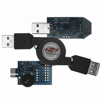
Base Adapter, C8051F330 Daughter Card and USB Cable
Interface Type
USB
Operating Supply Voltage
2.7 V to 3.6 V
Accessory Type
Starter Kit Adapter
Convert From
USB
Convert To
Daughter Board
Development Tool Type
Hardware - Daughter Card
Mcu Supported Families
ToolStick C8051F330
Rohs Compliant
Yes
Lead Free Status / RoHS Status
Contains lead / RoHS non-compliant
For Use With/related Products
C8051F300
Lead Free Status / Rohs Status
Lead free / RoHS Compliant
For Use With
C8051F330
Lead Free Status / RoHS Status
Lead free / RoHS Compliant, Contains lead / RoHS non-compliant
Other names
336-1348


To olSt ick-F 33 0DC
6.4. Viewing and Modifying Registers
All registers on the device can be viewed and modified when the device is in a halted state. The registers are
grouped together according to which peripheral or part of hardware they belong. As an example, this guide shows
how to open the ADC0 Debug Window and disable the ADC0 directly from the IDE.
1. Open the ADC0 Debug Window from the View → Debug Windows → SFR’s → ADC0 menu option. The
2. In the debug window, change the value of ADC0CN from 0x82 to 0x02. This value turns off the ADC on the
3. To write this new value to the device, select Refresh from the Debug Menu or click the Refresh button in the
4. Click “Go” to resume running the device with the new ADC0CN value.
5. Turn the potentiometer on the daughter card and notice that it has no effect on the blinking rate of the LED.
6. Re-enable the ADC by writing 0x82 to the ADC0CN and clicking the Refresh button.
Changing the values of registers does not require recompiling the code and redownloading the firmware. At any
time, the device can be halted and the values of the registers can be changed. After selecting “Go”, the firmware
will continue execution using the new values. This capability greatly speeds up the debugging process. See the
data sheet for the C8051F330 device for the definitions and usage for all registers.
The debug windows for other sets of registers are found in the View → Debug Windows → SFR’s menu.
8
ADC0 Debug Window appears on the right-hand side of the IDE. In this window, the ADC0CN register is shown.
This register is used to enable and configure the on-chip ADC. When the firmware is running, the ADC0CN
register reads as 0x82 indicating that the ADC is running.
target microcontroller.
toolbar.
Rev. 0.3
Related parts for TOOLSTICKSK
Image
Part Number
Description
Manufacturer
Datasheet
Request
R

Part Number:
Description:
NiCd - Nickel Cadmium Battery 9.6V 1500MAH
Manufacturer:
FDK Batteries (Formerly Sanyo)
Part Number:
Description:
Battery; Tool; NiCAD; 2.4V; 2400mah
Manufacturer:
Dantona Industries, Inc.
Datasheet:
Part Number:
Description:
Battery, Tool, Dewalt Compatable Replacement Battery, 18v, 1500mAh, Nicad
Manufacturer:
Dantona Industries, Inc.
Datasheet:
Part Number:
Description:
MILWAUKEE CORDLESS DRILL REPLACEMENT BATTERY, 12V, 1.3A
Manufacturer:
MILWAUKEE TOOL

Part Number:
Description:
TOOL-125, 12, 2400, NI-CD, MILWAUKEE:
Manufacturer:
DANTONA INDUSTRIES
Part Number:
Description:
Unspecified Battery types 2.4V 2500mAh EY9021
Manufacturer:
Unspecified
Part Number:
Description:
NiCd - Nickel Cadmium Battery 18V 2400mAh DeWalt Replacement
Manufacturer:
Unspecified
Part Number:
Description:
NiCd - Nickel Cadmium Battery 18V 2200mah
Manufacturer:
Unspecified
Part Number:
Description:
NiCd - Nickel Cadmium Battery 2.4V 1500mAh EY9021
Manufacturer:
Unspecified

Part Number:
Description:
SMD/C�/SINGLE-ENDED OUTPUT SILICON OSCILLATOR
Manufacturer:
Silicon Laboratories Inc
Part Number:
Description:
Manufacturer:
Silicon Laboratories Inc
Datasheet:
Part Number:
Description:
N/A N/A/SI4010 AES KEYFOB DEMO WITH LCD RX
Manufacturer:
Silicon Laboratories Inc
Datasheet:
Part Number:
Description:
N/A N/A/SI4010 SIMPLIFIED KEY FOB DEMO WITH LED RX
Manufacturer:
Silicon Laboratories Inc
Datasheet: