XCARD XK-1 XMOS, XCARD XK-1 Datasheet
XCARD XK-1
Specifications of XCARD XK-1


Related parts for XCARD XK-1


XCARD XK-1 Summary of contents
Page 1
... XK-1 Hardware Manual Publication Date: 2009/12/21 Copyright © 2009 XMOS Ltd. All Rights Reserved. Version 1.2.2 ...
Page 2
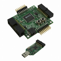
... The XK low cost development board intended for exploring and designing event-driven processor designs. It comprises a single XS1-L1 device, 128KBytes SPI FLASH memory, four LEDs and two press-button switches. Two XMOS Links allow you to link multiple XK-1 boards together in a chain, two I/O expansion areas are provided for connecting additional components to the XK-1, and an XTAG-2 debug adapter can be connected to debug the XK-1 board with a PC ...
Page 3
... I/O pins to the expansion areas The processor has ports that are directly connected to the I/O pins. Examples of how to write software that interfaces over these ports with the XK-1 components is provided in the document Programming XC for XMOS Devices available from the XMOS website. 3 User LEDs [C] The XK-1 provides four user LEDs that can be driven by software ...
Page 4
... The switches are connected to two pins, which are mapped to ports as described in the table on the next page. The push-button switch pins are active low. Pin Port Processor XD28 P4F0 PORT_LED XD29 P4F1 PORT_LED XD30 P4F2 PORT_LED XD31 P4F3 PORT_LED Pin Port Processor XD34 P1K0 PORT_BUT_1 XD35 P1L0 PORT_BUT_2 www.xmos.com 4/14 ...
Page 5
... The XK-1 includes two XSYS 20-way IDC Headers, which can be used to link to an XTAG-2 debug adapter for debugging programs on the board connect additional XK-1 boards together in a chain. The XSYS connector provides pins for JTAG control, system reset, processor debug, two UART links and two XMOS Links. Pin Signal 1 3V3 ...
Page 6
... No UART hardware is provided. Instead, two UART pins are mapped to ports, as shown in the table below UART is required, it can be implemented in software by sampling and driving these ports at the required rate. The XTAG-2 performs a UART-to-USB conversion on these pins, which is interfaced by a proprietary XMOS terminal emulator. Pin Port Processor ...
Page 7
... GND XD6 XD7 XD8 XD9 XD10 XD11 5V GND Each expansion header provides a bank of 12 I/O pins, which are mapped to the ports as described in the table on the next page, and four power/ground pins. www.xmos.com 7/14 GND 5V XD23 XD22 XD21 XD20 XD19 XD18 GND ...
Page 8
... Port Processor P1A0 P1B0 P4A0 P8A0 P4A1 P8A1 P4B0 P8A2 P4B1 P8A3 GPIO_A P4B2 P8A4 P4B3 P8A5 P4A2 P8A6 P4A3 P8A7 P4C0 P8B0 P4C1 P8B1 P4D0 P8B2 P4D1 P8B3 GPIO_B P4D2 P8B4 P4D3 P8B5 P4C2 P8B6 P4C3 P8B7 www.xmos.com 8/14 ...
Page 9
... Some of the I/O pins on the processor are configured as an additional 2-bit XMOS Link. The mapping of XMOS Links to the pins is shown in the table below. Some of the I/O pins on the expansion areas can also be configured as 2-bit XMOS Links. The mapping of XMOS Links to the headers is shown in the table below. ...
Page 10
... The voltage is converted by the on-board regulator to the 1V and 3V3 supplies used by the components. 10 Dimensions The XK-1 dimensions are 50 x 50mm. The mounting holes are 3mm in diameter. Pin Port Processor XD36 P1M0 PORT_SPI_MISO XD37 P1N0 PORT_SPI_SS XD38 P1O0 PORT_SPI_CLK XD39 P1P0 PORT_SPI_MOSI www.xmos.com 10/14 ...
Page 11
... XTO 11.1 I/O Port-to-Pin Mapping The table on the following page provides a full description of the port-to-pin mappings described throughout this document. GPIO HEADERS A, B XS1-L1 PORT_SPI_MISO PORT_SPI_SS PORT_SPI_CLK RST PORT_SPI_MOSI SPI CLOCK FLASH MEMORY www.xmos.com 11/14 TDO TDOC TMS TCK TRST_N DEBUG ...
Page 12
... P4F1 P8C3 PORT_LED P4F2 P8C4 P4F3 P8C5 P4E2 P8C6 P4E3 P8C7 P1K0 PORT_BUT_1 P1L0 PORT_BUT_2 P1M0 P8D0 PORT_SPI_MISO P1N0 P8D1 PORT_SPI_SS P1O0 P8D2 PORT_SPI_CLK P1P0 P8D3 PORT_SPI_MOSI P8D4 P8D5 P8D6 P8D7 XLC1_in XLC0_in XLC0_out XLC1_out XLD1_in XLD0_in XLD0_out XLD1_out www.xmos.com 12/14 ...
Page 13
... The following table lists the defined identifiers defined in the XMOS Tools ver- sion 9.9.1 for the XK-1: To provide backward compatibility with source code written using the version 9.9.0 XN fi ...
Page 14
... XMOS Ltd. is the owner or licensee of this design, code, or Information (collectively, the “Information”) and is providing it to you “AS IS” with no warranty of any kind, express or implied and shall have no liability in relation to its use. XMOS Ltd. makes no representation that the Information, or any particular implementation thereof will be free from any claims of infringement and again, shall have no liability in relation to any such claims ...