DM240312 Microchip Technology, DM240312 Datasheet - Page 41
DM240312
Manufacturer Part Number
DM240312
Description
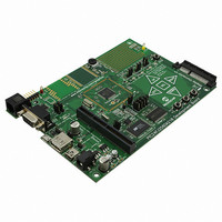
BOARD DEV PIC24FJ256DA210
Manufacturer
Microchip Technology
Series
dsPIC™r
Type
MCUr
Specifications of DM240312
Contents
Board
Processor To Be Evaluated
PIC24FJ256DA210
Data Bus Width
16 bit
Interface Type
RS-232, USB, Ethernet, SPI, UART
Operating Supply Voltage
9 V to 15 V
Silicon Manufacturer
Microchip
Core Architecture
PIC
Core Sub-architecture
PIC24
Silicon Core Number
PIC24F
Silicon Family Name
PIC24FJxxDAxxx
Kit Contents
Board
Lead Free Status / RoHS Status
Lead free / RoHS Compliant
For Use With/related Products
PIC24FJ256DA210
Lead Free Status / Rohs Status
Lead free / RoHS Compliant
Available stocks
Company
Part Number
Manufacturer
Quantity
Price
Company:

Part Number:
DM240312
Manufacturer:
Microchip Technology
Quantity:
135
Company:
Part Number:
DM240312
Manufacturer:
MICROCHIP
Quantity:
12 000


2010 Microchip Technology Inc.
4.4.3.2
The UART’s RX signal is mapped to only one pin (RD0) of the microcontroller. This pin
is also used by the development board to optionally control the backlight for the display
daughter board; all functions are multiplexed through the same jumper, JP12. If either
of the backlight control options is selected, the UART becomes unavailable to the exter-
nal RS-232 port.
4.4.4
The PIC24FJ256DA210 Development Board can support TFT, MSTN and CSTN
displays. Displays of 4, 8 and 16-bit data widths are supported. The 64-pin display Con-
nector V1 (J3) (on the right hand side bottom corner of the board) is provided for con-
nection of Microchip display boards.
4.4.4.1
When developing applications using TFT displays and the Graphics Display Prototype
Board, the 16-bit display bus can be used to send 16-bit RGB data (5-6-5 bits respec-
tively) to a standard 24-bit (8-8-8) or 18-bit (6-6-6) RGB display. To do this, color data
from the microcontroller is mapped to the Most Significant bits (MSbs) of the display.
The Least Significant bit lines of the display (3-2-3 for 24-bit displays, 1-0-1 for 18-bit)
are then tied to the MSb. This technique allows full brightness whenever the MSb is ‘1’,
and full blackness when the MSb is ‘0’. The controller-to-display data mapping is
detailed in Table 4-5.
TABLE 4-5:
4.4.4.2
The development board can directly interface with STN displays (both CSTN and
MSTN) of 4, 8 or 16-bit data width. The mapping of graphics data to the display data
input is described in Table 4-6. Configuration of the different data widths is done by the
graphics controller module through the register interface. Refer to the
“PIC24FJ256DA210 Family Data Sheet” (DS39969) for more information.
TABLE 4-6:
RED
GREEN
BLUE
Graphics Data Pins (GDx)
Graphics Data Pins (GDx)
GD<15:11>
GD<10:5>
GD<15:8>
GD<4:0>
GD<3:0>
GD<7:4>
GD<15>
GD<10>
UART AND DISPLAY BACKLIGHT (RX SIGNAL)
Graphics Port
TFT AND STN INTERFACES
STN INTERFACES
GD<4>
RGB INTERFACE MAPPING FOR TFT DISPLAYS
STN INTERFACE MAPPING
Development Board Hardware
18-Bit RGB Display
Unused
Unused
M<3:0>
4-bit
Green<5:0>
Green<5>
Blue<5:1>
Red<5:1>
Blue<0>
Red<0>
(6-6-6)
M<3:0>
M<7:4>
Unused
8-bit
24-Bit RGB Display
Green<7:2>
Green<1:0>
Blue<7:3>
Blue<2:0>
Red<7:3>
Red<2:0>
(8-8-8)
DS51911A-page 41
M<15:8>
M<3:0>
M<7:4>
16-bit
Related parts for DM240312
Image
Part Number
Description
Manufacturer
Datasheet
Request
R

Part Number:
Description:
Manufacturer:
Microchip Technology Inc.
Datasheet:
Part Number:
Description:
Manufacturer:
Microchip Technology Inc.
Datasheet:
Part Number:
Description:
Manufacturer:
Microchip Technology Inc.
Datasheet:
Part Number:
Description:
Manufacturer:
Microchip Technology Inc.
Datasheet:
Part Number:
Description:
Manufacturer:
Microchip Technology Inc.
Datasheet:
Part Number:
Description:
Manufacturer:
Microchip Technology Inc.
Datasheet:
Part Number:
Description:
Manufacturer:
Microchip Technology Inc.
Datasheet:
Part Number:
Description:
Manufacturer:
Microchip Technology Inc.
Datasheet: