C8051F540-TB Silicon Laboratories Inc, C8051F540-TB Datasheet - Page 7
C8051F540-TB
Manufacturer Part Number
C8051F540-TB
Description
BOARD PROTOTYPE W/C8051F540
Manufacturer
Silicon Laboratories Inc
Type
MCUr
Specifications of C8051F540-TB
Contents
Board
Processor To Be Evaluated
C8051F54x
Processor Series
C8051F54x
Interface Type
USB
Operating Supply Voltage
5 V
Lead Free Status / RoHS Status
Lead free / RoHS Compliant
For Use With/related Products
C8051F54x
Lead Free Status / Rohs Status
Lead free / RoHS Compliant
Other names
336-1672


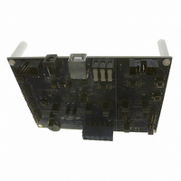
7. Target Board
The C8051F540 Development Kit includes a target board with a C8051F540 (Side A) and C8051F542 (Side B)
device pre-installed for evaluation and preliminary software development. Numerous input/output (I/O) connections
are provided to facilitate prototyping using the target board. Refer to Figure 3 for the locations of the various I/O
connectors. Figure 4 on page 9 shows the factory default shorting block positions. A summary of the signal names
and headers is provided in Table 9 on page 15.
P4
J18
P1
P5
TB1
J1-J3
J8
J9, J10
J13
J15
J16
J17
J20
P2
TB3
J4
J5-7
J11
J12
J19
P3
Header to choose between +5V from Debug Adapter (P2) or +5V from on-board regulator (U4)
Connect V_HIGH node from TB1 LIN header to +5V regulator input for board power
Power connector (accepts input from 7 to 15 VDC unregulated power adapter)
USB connector (connects to PC for serial communication)
Shared LIN Connector for Side A and B MCUs for external nodes
Side A: Port 0 through Port 2 headers
Side A: Connects +5V net to VIO and VREGIN of the MCU
Side A: External crystal enable connectors
Side A: Connects decoupling capacitors C28 and C29 for MCU VREF (P0.0)
Side A: Connects VIO to VIO_A_SRC which powers the R22 potentiometer, the RST_A
Side A: Connects P1.3_A LED and P1.4_A Switch to MCU port pins
Side A: Connects MCU to two separate transceivers (UART(U3), and LIN(T2))
Side A: Connects R27 potentiometer to port pin 1.2
Side A: DEBUG connector for Debug Adapter interface
Side A: Power supply terminal block
Side B: Connects +5V net to VIO and VREGIN of the MCU
Side B: Port 0 through Port 2 headers
Side B: Connects P1.3_B LED and P1.4_B Switch to MCU port pins
Side B: Connects MCU to LIN transceiver (T1)
Side B: Connects decoupling capacitors C41 and C42 for MCU VREF (P0.0)
Side B: DEBUG connector for Debug Adapter interface
pin pull-up, and P1.4_A Switch pull-up.
Rev. 0.1
C8051F540DK
7
Related parts for C8051F540-TB
Image
Part Number
Description
Manufacturer
Datasheet
Request
R

Part Number:
Description:
SMD/C°/SINGLE-ENDED OUTPUT SILICON OSCILLATOR
Manufacturer:
Silicon Laboratories Inc
Part Number:
Description:
Manufacturer:
Silicon Laboratories Inc
Datasheet:
Part Number:
Description:
N/A N/A/SI4010 AES KEYFOB DEMO WITH LCD RX
Manufacturer:
Silicon Laboratories Inc
Datasheet:
Part Number:
Description:
N/A N/A/SI4010 SIMPLIFIED KEY FOB DEMO WITH LED RX
Manufacturer:
Silicon Laboratories Inc
Datasheet:
Part Number:
Description:
N/A/-40 TO 85 OC/EZLINK MODULE; F930/4432 HIGH BAND (REV E/B1)
Manufacturer:
Silicon Laboratories Inc
Part Number:
Description:
EZLink Module; F930/4432 Low Band (rev e/B1)
Manufacturer:
Silicon Laboratories Inc
Part Number:
Description:
I°/4460 10 DBM RADIO TEST CARD 434 MHZ
Manufacturer:
Silicon Laboratories Inc
Part Number:
Description:
I°/4461 14 DBM RADIO TEST CARD 868 MHZ
Manufacturer:
Silicon Laboratories Inc
Part Number:
Description:
I°/4463 20 DBM RFSWITCH RADIO TEST CARD 460 MHZ
Manufacturer:
Silicon Laboratories Inc
Part Number:
Description:
I°/4463 20 DBM RADIO TEST CARD 868 MHZ
Manufacturer:
Silicon Laboratories Inc
Part Number:
Description:
I°/4463 27 DBM RADIO TEST CARD 868 MHZ
Manufacturer:
Silicon Laboratories Inc
Part Number:
Description:
I°/4463 SKYWORKS 30 DBM RADIO TEST CARD 915 MHZ
Manufacturer:
Silicon Laboratories Inc
Part Number:
Description:
N/A N/A/-40 TO 85 OC/4463 RFMD 30 DBM RADIO TEST CARD 915 MHZ
Manufacturer:
Silicon Laboratories Inc
Part Number:
Description:
I°/4463 20 DBM RADIO TEST CARD 169 MHZ
Manufacturer:
Silicon Laboratories Inc