C8051F930-TB Silicon Laboratories Inc, C8051F930-TB Datasheet - Page 16
C8051F930-TB
Manufacturer Part Number
C8051F930-TB
Description
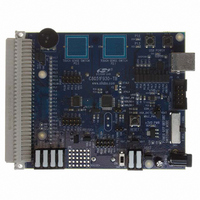
BOARD TARGET/PROTO W/C8051F930
Manufacturer
Silicon Laboratories Inc
Type
MCUr
Specifications of C8051F930-TB
Contents
Board
Processor To Be Evaluated
C8051F930
Processor Series
C8051F9xx
Data Bus Width
8 bit
Interface Type
I2C, UART, SPI
Maximum Operating Temperature
+ 85 C
Minimum Operating Temperature
- 40 C
Operating Supply Voltage
0.9 V to 3.6 V
Lead Free Status / RoHS Status
Lead free / RoHS Compliant
For Use With/related Products
C8051F930
Lead Free Status / Rohs Status
Lead free / RoHS Compliant
Other names
336-1472


C8051F930-DK
7.3. System Clock Sources
7.3.1. Internal Oscillators
The C8051F930 device installed on the target board features a factory calibrated programmable high-frequency
internal oscillator (24.5 MHz base frequency, ±2%) and a low power internal oscillator (20 MHz ±10%). After each
reset, the low power oscillator divided by 8 results in a default system clock frequency of 2.5 MHz (±10%). The
selected system clock and the system clock divider may be configured by software for operation at other
frequencies. For low-frequency operation, the C8051F930 features a smaRTClock real time clock. A 32.768 kHz
Watch crystal (Y2) is included on the target board. If you wish to operate the C8051F930 device at a frequency not
available with the internal oscillators, an external crystal may be used. Refer to the C8051F93x-C8051F92x data
sheet for more information on configuring the system clock source.
7.3.2. External Oscillator Options
The target board is designed to facilitate the installation of an external crystal (Y1). Install a 10 M resistor at R9
and install capacitors at C20 and C21 using values appropriate for the crystal you select. If you wish to operate the
external oscillator in capacitor or RC mode, options to install a capacitor or an RC network are also available on the
target board. Populate C21 for capacitor mode, and populate R16 and C21 for RC mode. Refer to the C8051F93x-
C8051F92x data sheet for more information on the use of external oscillators.
7.4. Port I/O Headers (J2, J3, J4, J6)
Access to all Port I/O on the C8051F930 is provided through the headers J2, J3, and J4. The header J6 provides
access to the ground plane for easy clipping of oscilloscope probes.
16
Rev. 0.5
Related parts for C8051F930-TB
Image
Part Number
Description
Manufacturer
Datasheet
Request
R

Part Number:
Description:
SMD/C°/SINGLE-ENDED OUTPUT SILICON OSCILLATOR
Manufacturer:
Silicon Laboratories Inc
Part Number:
Description:
Manufacturer:
Silicon Laboratories Inc
Datasheet:
Part Number:
Description:
N/A N/A/SI4010 AES KEYFOB DEMO WITH LCD RX
Manufacturer:
Silicon Laboratories Inc
Datasheet:
Part Number:
Description:
N/A N/A/SI4010 SIMPLIFIED KEY FOB DEMO WITH LED RX
Manufacturer:
Silicon Laboratories Inc
Datasheet:
Part Number:
Description:
N/A/-40 TO 85 OC/EZLINK MODULE; F930/4432 HIGH BAND (REV E/B1)
Manufacturer:
Silicon Laboratories Inc
Part Number:
Description:
EZLink Module; F930/4432 Low Band (rev e/B1)
Manufacturer:
Silicon Laboratories Inc
Part Number:
Description:
I°/4460 10 DBM RADIO TEST CARD 434 MHZ
Manufacturer:
Silicon Laboratories Inc
Part Number:
Description:
I°/4461 14 DBM RADIO TEST CARD 868 MHZ
Manufacturer:
Silicon Laboratories Inc
Part Number:
Description:
I°/4463 20 DBM RFSWITCH RADIO TEST CARD 460 MHZ
Manufacturer:
Silicon Laboratories Inc
Part Number:
Description:
I°/4463 20 DBM RADIO TEST CARD 868 MHZ
Manufacturer:
Silicon Laboratories Inc
Part Number:
Description:
I°/4463 27 DBM RADIO TEST CARD 868 MHZ
Manufacturer:
Silicon Laboratories Inc
Part Number:
Description:
I°/4463 SKYWORKS 30 DBM RADIO TEST CARD 915 MHZ
Manufacturer:
Silicon Laboratories Inc
Part Number:
Description:
N/A N/A/-40 TO 85 OC/4463 RFMD 30 DBM RADIO TEST CARD 915 MHZ
Manufacturer:
Silicon Laboratories Inc
Part Number:
Description:
I°/4463 20 DBM RADIO TEST CARD 169 MHZ
Manufacturer:
Silicon Laboratories Inc