CY8CKIT-001 Cypress Semiconductor Corp, CY8CKIT-001 Datasheet - Page 35
CY8CKIT-001
Manufacturer Part Number
CY8CKIT-001
Description
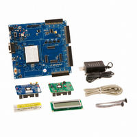
KIT DEV FOR PSOC3/5
Manufacturer
Cypress Semiconductor Corp
Series
PSoC® CapSenser
Type
MCUr
Datasheets
1.CY8CKIT-001.pdf
(2 pages)
2.CY8CKIT-001.pdf
(5 pages)
3.CY8CKIT-001.pdf
(116 pages)
4.CY8CKIT-001.pdf
(12 pages)
Specifications of CY8CKIT-001
Contents
Board, CD, CY8C29 & CY8C38 Modules, MiniProg3 Programmer/Debugger, Power Supply
Processor To Be Evaluated
CY8C29, CY8C38
Interface Type
RS-232, USB, JTAG
Operating Supply Voltage
3.3 V, 5 V
Lead Free Status / RoHS Status
Lead free / RoHS Compliant
For Use With/related Products
PSoC 1, PSoC 3 and PSoC 5
Lead Free Status / Rohs Status
Lead free / RoHS Compliant
Other names
428-2961
Available stocks
Company
Part Number
Manufacturer
Quantity
Price
Company:

Part Number:
CY8CKIT-001A
Manufacturer:
Cypress Semiconductor
Quantity:
135


3.1.2.2
CY8CKIT-001 PSoC Development Kit Guide, Doc. # 001-48651 Rev. **
main.c
/*******************************************************************************
* File Name: main.c
*
* Description:
*
*
*
*
********************************************************************************
/******************************************************************************
*
ADC)
*
*
*
*
*
*******************************************************************************/
/******************************************************************************
*
*
*
*******************************************************************************/
/******************************************************************************
*
*
*
*
*
*
*
*
*
*
*
*
*
*
*******************************************************************************/
#include <m8c.h>
#include “PSoCAPI.h”
unsigned int wADCResult; // Holds the integer ADC result
void main()
{
This file provides source code for the ADC to LCD example project. The
firmware takes a voltage output from a potentiometer and displays the raw
counts on an LCD.
PGA Settings:(The PGA buffers the potentiometer voltage on P0.1 into the *
LCD Settings:
DelSig Settings:
The ADC can read full range values from 0-5V, if the Ref Mux setting is
resolution of 9 bits, this is achieved by selecting the appropriate
configuration when placing the UM.
DelSig_1_Start(DelSig_1_HIGHPOWER); //Initialize the ADC
LCD_1_Start();
PGA_1_Start(PGA_1_HIGHPOWER);//Initialize the PGA, PGA used to buffer
Gain
Input
Reference = AGND
AnalogBus = Disable
LCDPort
BarGraph
DataFormat
DataClock
ClockPhase
PosInput
NegInput
NegInputGain = Disconnected
PWM Output
PulseWidth
selected as (Vdd/2)+/- (Vdd/2) and Vdd = 5V. The ADC is configured for a
= 1
= AnalogColumn_InputMUX_0
= Port_2
= Disable
= Unsigned
= VC1
= Normal
= ACB00 (PGA_1)
= ACB00
= None
= 1
//Initialize the LCD
// part specific constants and macros
// PSoC API definitions for all User Modules
*Note, this parameter is unused
*Note, this parameter is unused
// VC1 = 24MHz/12 = 2MHz
//input from the VR on P0.1 to the ADC
(P0.1)
Sample Projects
31
[+] Feedback
Related parts for CY8CKIT-001
Image
Part Number
Description
Manufacturer
Datasheet
Request
R

Part Number:
Description:
KIT DEV FOR PSOC3/5
Manufacturer:
Cypress Semiconductor Corp
Datasheet:

Part Number:
Description:
PSoC1/3/5 Development Kit
Manufacturer:
Cypress Semiconductor Corp
Datasheet:

Part Number:
Description:
KIT DEV PSOC PROC MODULE CY8C38
Manufacturer:
Cypress Semiconductor Corp

Part Number:
Description:
KIT DEV PSOC PROC MODULE CY8C29
Manufacturer:
Cypress Semiconductor Corp

Part Number:
Description:
KIT DEV PSOC ANALOG VOLTMETER
Manufacturer:
Cypress Semiconductor Corp
Datasheet:

Part Number:
Description:
KIT DEV PSOC5 FIRST TOUCH
Manufacturer:
Cypress Semiconductor Corp
Datasheet:

Part Number:
Description:
KIT DEV PSOC3 FIRSTTOUCH STARTER
Manufacturer:
Cypress Semiconductor Corp
Datasheet:
Part Number:
Description:
KIT DEV PROC MODULE PSOC5
Manufacturer:
Cypress Semiconductor Corp
Datasheet:

Part Number:
Description:
KIT PSOC CY8C28 FAMILY PROCESSOR
Manufacturer:
Cypress Semiconductor Corp
Datasheet:

Part Number:
Description:
KIT PSOC MINIPROG3 PROGRAM DEBUG
Manufacturer:
Cypress Semiconductor Corp
Datasheet:

Part Number:
Description:
KIT EVAL POWERLINE HIGH VOLT
Manufacturer:
Cypress Semiconductor Corp
Datasheet:

Part Number:
Description:
KIT PSOC FIRST TOUCH
Manufacturer:
Cypress Semiconductor Corp
Datasheet:

Part Number:
Description:
EVAL KIT WORLDTOUR2
Manufacturer:
Cypress Semiconductor Corp
Datasheet:

Part Number:
Description:
KIT UNIVERSAL CAPSENSE CTRLR
Manufacturer:
Cypress Semiconductor Corp
Datasheet:
