ST-LINK STMicroelectronics, ST-LINK Datasheet - Page 19
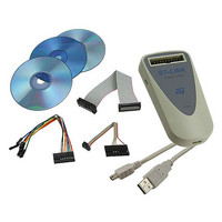
ST-LINK
Manufacturer Part Number
ST-LINK
Description
DEBUGGER/PROGRAMMER STM8 STM32
Manufacturer
STMicroelectronics
Type
In-Circuit Debugger/Programmerr
Datasheet
1.ST-LINK.pdf
(22 pages)
Specifications of ST-LINK
Contents
Module, Cables
Positions/sockets
1
Description/function
In-Circuit Programmer, Debugger
Core Architecture
ARM, STM8
Core Sub-architecture
Cortex - M3, STM8
Ic Product Type
In-Circuit Debugger / Programmer
For Use With/related Products
STM8, STM32
Lead Free Status / RoHS Status
Lead free / RoHS Compliant
Other names
497-10484
ST-LINK
ST-LINK
Available stocks
Company
Part Number
Manufacturer
Quantity
Price

Company:
Part Number:
ST-LINK/V2
Manufacturer:
P&S
Quantity:
1 700
Part Number:
ST-LINK/V2
Manufacturer:
ST
Quantity:
20 000
Part Number:
ST-LINK/V2-ISOL
Manufacturer:
ST
Quantity:
20 000


UM0892
STM32 ST-LINK Utility Command Line Interface (CLI)
e.g. -OB RDP=0 IWDG_SW=1 nRST_STOP=0 Data0=0xAA
Data1=0xBC.
This command line:
- Disables Read Protection (Level 0),
- Sets the IWDG_SW to 1,
- Sets the nRST_STOP to 0,
- Sets Data0 option byte,
- Sets Data1 option byte.
Description: This cammand configures the option bytes.
Parameters description:
RDP=<Level> : Set the Flash memory read protection
level. Level could be one of the following levels:
0 : Protection disabled.
1 : Protection enabled.
2 : Protection enabled(debug and boot in SRAM features
are DISABLED).
Note: Level 2 is available on available on STM32 F-2 and
STM32 L-1 series only.
BOR_LEV=<Level>: Set the Brownout Reset threshold level.
* For STM32 L-1 series:
0 : BOR OFF,1.45 to 1.55 V voltage range
1 : 1.69 to 1.8 V voltage range
2 : 1.94 to 2.1 V voltage range
3 : 2.3 to 2.49 V voltage range
4 : 2.54 to 2.74V voltage range
5 : 2.77 to 3.0 V voltage range
* For STM32 F-2 series:
0 : BOR OFF, 1.8 to 2.10 V voltage range
1 : 2.10 to 2.40 V voltage range
2 : 2.40 to 2.70 V voltage range
3 : 2.70 to 3.60 V voltage range
IWDG_SW=<Value>: <Value> should be be 0 or 1:
0 : Hardware independent watchdog
1 : Software independent watchdog
nRST_STOP=<Value>: <Value> should be be 0 or 1:
0 : Reset generated when CPU enters the Stop mode
1 : No reset generated.
nRST_STDBY=<Value>: <Value> should be be 0 or 1:
0 : Reset generated when CPU enters the Standby mode
1 : No reset generated.
BFB2=<Value>: <Value> should be be 0 or 1:
0 : Boot from Flash bank 2 when boot pins are set in boot
from user Flash position(default)
1 : Boot from Flash bank 1 when boot pins are set in boot
from user Flash position(default).
Doc ID 16987 Rev 5
19/22
Related parts for ST-LINK
Image
Part Number
Description
Manufacturer
Datasheet
Request
R

Part Number:
Description:
STMicroelectronics [RIPPLE-CARRY BINARY COUNTER/DIVIDERS]
Manufacturer:
STMicroelectronics
Datasheet:
Part Number:
Description:
STMicroelectronics [LIQUID-CRYSTAL DISPLAY DRIVERS]
Manufacturer:
STMicroelectronics
Datasheet:

Part Number:
Description:
BOARD EVAL FOR MEMS SENSORS
Manufacturer:
STMicroelectronics
Datasheet:
Part Number:
Description:
NPN TRANSISTOR POWER MODULE
Manufacturer:
STMicroelectronics
Datasheet:
Part Number:
Description:
TURBOSWITCH ULTRA-FAST HIGH VOLTAGE DIODE
Manufacturer:
STMicroelectronics
Datasheet:
Part Number:
Description:
Manufacturer:
STMicroelectronics
Datasheet:
Part Number:
Description:
DIODE / SCR MODULE
Manufacturer:
STMicroelectronics
Datasheet:
Part Number:
Description:
DIODE / SCR MODULE
Manufacturer:
STMicroelectronics
Datasheet:
Part Number:
Description:
Search -----> STE16N100
Manufacturer:
STMicroelectronics
Datasheet:
Part Number:
Description:
Search ---> STE53NA50
Manufacturer:
STMicroelectronics
Datasheet:
Part Number:
Description:
NPN Transistor Power Module
Manufacturer:
STMicroelectronics
Datasheet:
Part Number:
Description:
DIODE / SCR MODULE
Manufacturer:
STMicroelectronics
Datasheet: