Z86CCP01ZEM Zilog, Z86CCP01ZEM Datasheet - Page 5
Z86CCP01ZEM
Manufacturer Part Number
Z86CCP01ZEM
Description
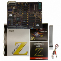
Z8 EMULATOR/PROGRAMMER BOARD
Manufacturer
Zilog
Series
Z8 OTPr
Type
In-Circuit Emulator Systemr
Datasheet
1.Z86CCP00ZAC.pdf
(8 pages)
Specifications of Z86CCP01ZEM
Contents
Circuit Board with Chips, Programming Sockets, Sockets with Target Cable, Interface Connector, Power Cable and Manual
For Use With/related Products
Zilog Z8® Series Microcontrollers
Lead Free Status / RoHS Status
Contains lead / RoHS non-compliant
Other names
269-2002
Z86CCP00ZEM
Z86CCP00ZEM


Zilog
LIMITATIONS
1. Typing into the File Name box in order to change the
2. Switching ICEBOX™ emulators without quitting the
3. The maximum loadable symbols is 32,768, provided
4. The keyboard and mouse will lock up if the screen
5. Although GUI 3.00 and later support baud rates up to
6. The initial blue Zilog screen can be distorted by other
7. Do not put a breakpoint at addresses after STOP
PRECAUTIONS
ALL Devices
1. GUI software versions prior to 3.00 are incompatible
2. For some 386 PCs, a baud rate of 19.2K or less is
CP97Z8X5301
drive in the file download and load symbol dialog
boxes is not anticipated by the GUI. Instead, use the
mouse in the Directories box as the workaround.
GUI is not supported and may cause unexpected
results.
there is enough system resource (memory).
saver supplied by Windows 3.1 times out while the
GUI software is waiting for the user to complete
entering a line of assembly code in the Debug window.
To recover, the user must reset the computer. The
workaround is to turn off the screen saver, set the
screen saver to a much longer time out value, finish
the line of code before the time-out occurs (press
ENTER), or use a different screen saver such as “After
Dark.” This problem may also exist at other points in
the GUI that request input from the user.
57.6K baud, the actual maximum usable rate may be
less due to limitations of the user’s hardware or
system software setup. The maximum usable rate is
determined by the user’s tolerance of the frequency of
communication errors.
active windows. This only affects the appearance, not
the functionality, of the GUI.
instruction. This will cause the program counter to
continue at that location after a Stop-Mode Recovery.
with hardware containing BOOTROM 3.00. The GUI
software may still boot, but will fail at some later point.
necessary because the Windows' communication
driver does not guarantee “reliable” operation above
9600 baud. On some slower 386 machines, selecting
a high baud rate might crash the Windows'
environment or result in excessive communication
errors.
8. Single-stepping into the Halt instruction will cause an
9. Clicking on the HALT button does not always halt the
10. RC oscillator emulation is not supported.
11. Since the emulator uses the Z86C50 ICE chip, Port 1
12. When the software enters a STOP mode and the
13. Although the GUI displays two timers (T0,T1) for
14. Multiple emulators instances cannot be used when the
3. When simultaneously running two different GUI
4. The emulator cannot be operated while performing
5. Executing GUI. The GUI will occasionally continue to
A workaround is to do a JUMP 000D and execute with
GO. This will not issue a POR reset.
device.
ICEBOX “Fatal Error” message to be displayed on the
screen. The ICE chip must be reset, either by /Reset
pin on the target board or by resetting the whole
ICEBOX by pressing the emulator MASTER RESET
button at the back of the emulator.
ICEBOX execution. If the application goes into Stop
Mode or Halt Mode, the only way to halt the emulator
execution is by doing a Stop-Mode Recovery (as
defined by the user program). You may also reset the
application using the emulator MASTER RESET
button; however, this will reset the whole ICEBOX.
cannot be configured to Low EMI mode. Bit 4 in PCON
registers must be set to logic “1”.
Note: This is not a problem with the actual emulated
HALT control button in the GUI software is pressed,
any SMR source on the application board is activated.
The emulator will then jump back to address 000C,
which is normal. But when continuing the program with
a GO command from 000C, a POR reset is performed,
resetting all control registers.
Z86C02/E02, only Timer1 is valid for these devices.
OTP Programming Window is open.
versions on two different Communication Ports, the
former executed version is used for both emulators.
This is a Windows Operating System bug.
ESD/EMI testing on the target board.
indicate “Executing” after a Halt instruction. Pushing
the GO button will then result in Executing. (Executing
showing at the top of the screen.)
Z8® CCP™ In-Circuit Emulator
5
1
Related parts for Z86CCP01ZEM
Image
Part Number
Description
Manufacturer
Datasheet
Request
R

Part Number:
Description:
Communication Controllers, ZILOG INTELLIGENT PERIPHERAL CONTROLLER (ZIP)
Manufacturer:
Zilog, Inc.
Datasheet:

Part Number:
Description:
KIT DEV FOR Z8 ENCORE 16K TO 64K
Manufacturer:
Zilog
Datasheet:

Part Number:
Description:
KIT DEV Z8 ENCORE XP 28-PIN
Manufacturer:
Zilog
Datasheet:

Part Number:
Description:
DEV KIT FOR Z8 ENCORE 8K/4K
Manufacturer:
Zilog
Datasheet:

Part Number:
Description:
KIT DEV Z8 ENCORE XP 28-PIN
Manufacturer:
Zilog
Datasheet:

Part Number:
Description:
DEV KIT FOR Z8 ENCORE 4K TO 8K
Manufacturer:
Zilog
Datasheet:
Part Number:
Description:
CMOS Z8 microcontroller. ROM 16 Kbytes, RAM 256 bytes, speed 16 MHz, 32 lines I/O, 3.0V to 5.5V
Manufacturer:
Zilog, Inc.
Datasheet:
Part Number:
Description:
Low-cost microcontroller. 512 bytes ROM, 61 bytes RAM, 8 MHz
Manufacturer:
Zilog, Inc.
Datasheet:
Part Number:
Description:
Z8 4K OTP Microcontroller
Manufacturer:
Zilog, Inc.
Datasheet:
Part Number:
Description:
CMOS SUPER8 ROMLESS MCU
Manufacturer:
Zilog, Inc.
Datasheet:
Part Number:
Description:
SL1866 CMOSZ8 OTP Microcontroller
Manufacturer:
Zilog, Inc.
Datasheet:
Part Number:
Description:
SL1866 CMOSZ8 OTP Microcontroller
Manufacturer:
Zilog, Inc.
Datasheet:
Part Number:
Description:
OTP (KB) = 1, RAM = 125, Speed = 12, I/O = 14, 8-bit Timers = 2, Comm Interfaces Other Features = Por, LV Protect, Voltage = 4.5-5.5V
Manufacturer:
Zilog, Inc.
Datasheet:
Part Number:
Description:
Manufacturer:
Zilog, Inc.
Datasheet: