CBC5300-24C Cymbet Corporation, CBC5300-24C Datasheet - Page 5
CBC5300-24C
Manufacturer Part Number
CBC5300-24C
Description
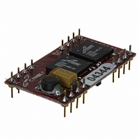
ENERCHIP EH CBC5300 MODULE
Manufacturer
Cymbet Corporation
Series
EnerChip™ EHr
Type
Energy Harvestingr
Datasheet
1.CBC5300-24C.pdf
(11 pages)
Specifications of CBC5300-24C
Module/board Type
Energy Harvesting Module
Input Voltage
0.25 V to 4 V
Output Voltage
3.6 V
Board Size
30.5 mm x 17.2 mm
Maximum Operating Temperature
+ 70 C
Minimum Operating Temperature
0 C
Product
Power Management Modules
Dimensions
30.5 mm x 17.2 mm
Lead Free Status / RoHS Status
Request inventory verification / Request inventory verification
For Use With/related Products
Thin Film Rechargeable Solid State Battery
Lead Free Status / Rohs Status
Lead free / RoHS Compliant
Other names
859-1000-5


Preliminary
Designing for Pulse Discharge Currents in Wireless Devices
Pulse discharge currents place special demands on batteries. Repeated delivery of pulse currents exceeding
the recommended load current of a given chemistry will diminish the useful life of the cell. The effects can be
severe, depending on the amplitude of the current and the particular cell chemistry and construction. Pulse
currents of tens of milliamperes are common in wireless sensor systems during transmit and receive modes.
Moreover, the internal impedance of the cell often results in an internal voltage drop that precludes the cell
from delivering the pulse current at the voltage necessary to operate the external circuit. One method of
mitigating such effects is to place a low Equivalent Series Resistance (ESR) capacitor across the battery. The
battery charges the capacitor between discharge pulses and the capacitor delivers the pulse current to the
load. Specifying the capacitance for a given battery in an application is a straightforward procedure, once a few
key parameters are known. The key parameters are:
•
•
•
•
•
•
Two equations will be used to calculate two unknown parameters:
Both formulae will assume that the capacitor ESR is sufficiently low to result in negligible internal voltage drop
while delivering the specified pulse current; consequently, only the battery resistance will be considered in
the formula used to compute capacitor charging time and only the load resistance will be considered when
computing the capacitance needed to deliver the discharge current.
The first step in creating a battery-capacitor couple for pulse current applications is to size the capacitance
using the following formula:
Discharge formula: C = t / R * [-ln (Vmin / Vmax)]
where:
C = output capacitance, in parallel with battery;
t = pulse duration;
R = load resistance = Vout(average) / Ipulse
Vmin and Vmax are determined by the combination of the battery voltage at a given state-of-charge and the
operating voltage requirement of the external circuit.
Once the capacitance has been determined, the capacitor charging time can be calculated using the following
formula:
Charge formula: t = R * C * [- ln (1 - Vmin / Vmax)]
where:
t = capacitor charging time, from Vmin to Vmax
R = battery resistance
C = output capacitance, in parallel with battery
DS-72-06 Rev06
Battery impedance (at temperature and state-of-charge)
Battery voltage (as a function of state-of-charge)
Operating temperature
Pulse current amplitude
Pulse current duration
Allowable voltage droop during pulse discharge
1) the output capacitance needed to deliver the specified pulse current of a known duration;
2) the latency time that must be imposed between pulses to allow the capacitor to be recharged by the
battery.
©2009 Cymbet Corporation • Tel: +1-763-633-1780 • www.cymbet.com
EnerChip EH CBC5300
Page 5 of 11
Related parts for CBC5300-24C
Image
Part Number
Description
Manufacturer
Datasheet
Request
R


Part Number:
Description:
ENERCHIP CC EVAL KIT
Manufacturer:
Cymbet Corporation
Datasheet:

Part Number:
Description:
ENERCHIP CC SEH EVAL KIT
Manufacturer:
Cymbet Corporation
Datasheet:

Part Number:
Description:
ENERCHIP EP ENERGY HARVEST EVAL
Manufacturer:
Cymbet Corporation
Datasheet: