DLP-IO20 DLP Design Inc, DLP-IO20 Datasheet - Page 3
DLP-IO20
Manufacturer Part Number
DLP-IO20
Description
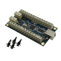
MODULE DATA-ACQUISITION 20-CH
Manufacturer
DLP Design Inc
Type
Motor / Motion Controllers & Driversr
Datasheet
1.DLP-IO20.pdf
(13 pages)
Specifications of DLP-IO20
Module/board Type
Data Acquisition, 20-Channel
Input Voltage
0 V to 5 V
Output Voltage
5 V
Board Size
91.5 mm x 48.3 mm x 23 mm
Interface Type
USB
Maximum Operating Temperature
+ 70 C
Minimum Operating Temperature
0 C
Product
Power Management Modules
Dimensions
91.5 mm x 48.3 mm x 23 mm
Lead Free Status / RoHS Status
Lead free / RoHS Compliant
For Use With/related Products
USB
Lead Free Status / Rohs Status
Lead free / RoHS Compliant
Other names
813-1027
DLP-IO20-G
DLP-IO20-G
Available stocks
Company
Part Number
Manufacturer
Quantity
Price
Company:

Part Number:
DLP-IO20
Manufacturer:
DLP Design
Quantity:
135


5.0 USB DRIVERS
USB drivers for the following operating systems are available for download from the DLP Design
website:
These drivers are available for download from the following page: http://www.dlpdesign.com/DNLD8/.
NOTE: If using the dual mode drivers from FTDI (CDM2.x.x) and you want to use the Virtual COM
Port (VCP) drivers then it may be necessary to disable the D2XX drivers first via Device Manager.
Right click on the entry under USB Controllers that appears when the DLP-IO20 is connected, select
Properties, select the Advanced tab, put a check in the option for “Load VCP” and click OK. Unplug
and replug the DLP-IO20 and a COM port should appear in Device Manager under Ports (COM &
LPT).
6.0 TERMINAL BLOCK PIN DEFINITIONS
The wiring terminals on the DLP-IO20 are explained in the following table.
R1
C1
S1
GND
P7
P6
P5
+5V
AN7
AN6
AN5
AN4
RA4
Pin Name
Rev. 1.0 (January 2009)
Description
Latching Relay 1 Reset Contact (see note 3)
Latching Relay 1 Common Contact (see note 3)
Latching Relay 1 Set Contact (see note 3)
Ground
Relay Driver Output P7. Driven by Darlington pair transistors powered by 5V from
the USB port. (see note 4)
Relay Driver Output P6. Driven by Darlington pair transistors powered by 5V from
the USB port. (see note 4)
Relay Driver Output P5. Driven by Darlington pair transistors powered by 5V from
the USB port. (see note 4)
VCC Output +5.0V. Limit current drawn from this pin to 100mA to avoid exceeding
the available current from the host USB port.
Analog Input AN7. Input voltage range is zero to +5V. (see note 1) Digital I/O AN7,
Configurable as a digital Input, a digital output (5V), or an open drain output (5V
MAX pullup). (see note 2)
Analog Input AN6. Input voltage range is zero to +5V. (see note 1) Digital I/O AN6,
Configurable as a digital Input, a digital output (5V), or an open drain output (5V
MAX pullup). (see note 2)
Analog Input AN5. Input voltage range is zero to +5V. (see note 1) Digital I/O AN5,
Configurable as a digital Input, a digital output (5V), or an open drain output (5V
MAX pullup). (see note 2)
Analog Input AN4. Input voltage range is zero to +5V. (see note 1) Digital I/O AN4,
Configurable as a digital Input, a digital output (5V), or an open drain output (5V
MAX pullup). (see note 2)
Digital I/O RA4, Configurable as a digital Input, a digital output (5V), or an open
drain output (5V MAX pullup). (see note 2)
J1 Prototyping Terminal Block Pin Definitions
Windows Server 2003
Windows XP x64
Windows 98, ME
Windows 2000
TABLE 1
3
Mac OSX
Mac OS9
Mac OS8
Linux
© DLP Design, Inc.
Related parts for DLP-IO20
Image
Part Number
Description
Manufacturer
Datasheet
Request
R

Part Number:
Description:
MODULE USB-TO-FPGA TOOL W/MANUAL
Manufacturer:
DLP Design Inc
Datasheet:

Part Number:
Description:
Interface Modules & Development Tools From FTDI USB-Seril CABL I/O3.3 2MM PIN
Manufacturer:
DLP Design Inc
Datasheet:

Part Number:
Description:
MODULE DATA-ACQUISITION 8-CH
Manufacturer:
DLP Design Inc
Datasheet:

Part Number:
Description:
Interface Modules & Development Tools DLP-245PL PACKAGED w/CCS Compiler
Manufacturer:
DLP Design Inc

Part Number:
Description:
Interface Modules & Development Tools DLP-245PB-G BOARD + CCS Compiler
Manufacturer:
DLP Design Inc
Datasheet:

Part Number:
Description:
Interface Modules & Development Tools DLP-TILT SENSOR ACCEL VIBRATION
Manufacturer:
DLP Design Inc

Part Number:
Description:
Zigbee / 802.15.4 Modules & Development Tools USE 626-DLP-RF2-Z
Manufacturer:
DLP Design Inc
Datasheet:

Part Number:
Description:
Interface Modules & Development Tools FLASH2 TARGET BOARD 18F2321 w/IDE 2k Ltd
Manufacturer:
DLP Design Inc

Part Number:
Description:
Interface Modules & Development Tools FLASH2 TARGET BOARD 16F917 w/IDE 2k Ltd
Manufacturer:
DLP Design Inc

Part Number:
Description:
Interface Modules & Development Tools RETRACTABLE USB CBL USB TO MINI USB
Manufacturer:
DLP Design Inc

Part Number:
Description:
MODULE USB-MCU FT245RL W/16F877A
Manufacturer:
DLP Design Inc
Datasheet:

Part Number:
Description:
MODULE USB-TO-FPGA TRAINING TOOL
Manufacturer:
DLP Design Inc
Datasheet:

Part Number:
Description:
MODULE USB-MCU FT232R W/18F2410
Manufacturer:
DLP Design Inc
Datasheet:

Part Number:
Description:
MODULE USB-MCU FT245RL W/SX48
Manufacturer:
DLP Design Inc
Datasheet:

Part Number:
Description:
MODULE USB-MCU FT2232D W/16F877A
Manufacturer:
DLP Design Inc
Datasheet: