ZXFV202N8EV Diodes Zetex, ZXFV202N8EV Datasheet
ZXFV202N8EV
Manufacturer Part Number
ZXFV202N8EV
Description
BOARD EVALUATION FOR ZXFV202
Manufacturer
Diodes Zetex
Specifications of ZXFV202N8EV
Main Purpose
Video, Amplifier, Single
Embedded
No
Utilized Ic / Part
ZXFV202
Primary Attributes
Current Feedback, 210MHz, 600V/us, ±5 V
Secondary Attributes
Gain of 1 or 2, 40mA Output
Lead Free Status / RoHS Status
Contains lead / RoHS non-compliant


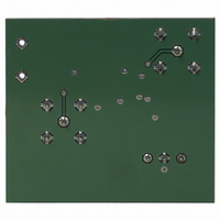
SINGLE CHANNEL VIDEO AMPLIFIER EVALUATION BOARD
Evaluation board description
The wide bandwidth of the ZXFV202 video amplifier
necessitates some care in the layout of the printed
circuit. For this reason Zetex has made available an
Evaluation Board.
The Evaluation Board layout serves as a useful
example for many applications, showing a practical
implementation of the advice given below.
Figures 1, 2 and 3 show the schematic and copper
layout of a double-sided printed circuit board suitable
for evaluation of the device in the laboratory.
BNC connector sockets allow connection to test
instruments via 50 cables. The output circuit includes
a resistor matching circuit to present a load of 150 to
the amplifier (equivalent to a 75
video line) and simultaneously provide 50
impedance.
The attenuation of this matching circuit is 15.45 dB. As
the amplifier is configured for a voltage gain of 2, the
overall gain is:
6 - 15.45 = -9.45dB.
ISSUE 1 - MAY 2004
back-terminated
Figure 1 Circuit schematic
output
1
PCB design
A continuous ground plane is required under the
device and its signal connection paths, to provide the
shortest possible ground return paths for signals and
power supply filtering.
A double-sided or multi-layer PCB construction is
required, with plated-through via holes providing
closely spaced low-inductance connections from some
components to the continuous ground plane (some of
these holes are not visible in the figures for the
Evaluation Board – artworks and NC drill output can be
provided if required).
Power supply filtering
For the power supply filtering, low inductance surface
mount capacitors are normally required. It has been
found that very good RF decoupling is provided on
each supply using a 1000pF NPO size 0805 or smaller
ceramic surface mount capacitor, closest to the device
pin, with an adjacent 0.1µF X7R capacitor. Other
configurations are possible and it may be found that a
single 0.01uF X7R capacitor on each supply gives good
results. However this should be supported by larger
decoupling capacitors elsewhere on the printed circuit
board. Values of 1 to 10 µF are recommended,
particularly where the voltage regulators are located
more than a few inches from the device. These larger
capacitors are recommended to be solid tantalum
electrolytic or ceramic types.
A parts list is provided on the next page.
ZXFV202N8EV
S E M I C O N D U C T O R S
Related parts for ZXFV202N8EV
Image
Part Number
Description
Manufacturer
Datasheet
Request
R

Part Number:
Description:
DIODE ZENER 13V 500MW SOD-123
Manufacturer:
Diodes Zetex
Datasheet:

Part Number:
Description:
DIODE ZENER 13V 200MW SOD-323
Manufacturer:
Diodes Zetex
Datasheet:

Part Number:
Description:
DIODE ZENER 27V 500MW MINIMELF
Manufacturer:
Diodes Zetex
Datasheet:
Part Number:
Description:
DIODE ZENER 16V 200MW SOD-323
Manufacturer:
Diodes Zetex
Datasheet:
Part Number:
Description:
DIODE ZENER 28V 500MW SOD-123
Manufacturer:
Diodes Zetex
Datasheet:

Part Number:
Description:
DIODE ZENER 6.2V 200MW SC70-3
Manufacturer:
Diodes Zetex
Datasheet:

Part Number:
Description:
DIODE ZENER 3.6V 350MW SOT23-3
Manufacturer:
Diodes Zetex
Datasheet:

Part Number:
Description:
DIODE ZENER 4.3V 350MW SOT23-3
Manufacturer:
Diodes Zetex
Datasheet:
Part Number:
Description:
DIODE ZENER 13V 350MW SOT23-3
Manufacturer:
Diodes Zetex
Datasheet:
Part Number:
Description:
DIODE ZENER 16V 350MW SOT23-3
Manufacturer:
Diodes Zetex
Datasheet:

Part Number:
Description:
DIODE SW ARRAY 80V 200MW SOT363
Manufacturer:
Diodes Zetex
Datasheet:

Part Number:
Description:
DIODE SCHOTTKY 45V16A TO220-3
Manufacturer:
Diodes Zetex
Datasheet:
Part Number:
Description:
DIODE SCHOTTKY 45V 20A TO220-3
Manufacturer:
Diodes Zetex
Datasheet:
Part Number:
Description:
DIODE SW FAST DUAL CC SOT23-3
Manufacturer:
Diodes Zetex
Datasheet:
Part Number:
Description:
DIODE HI SPEED SW CC 70V SOT23-3
Manufacturer:
Diodes Zetex
Datasheet:
ZXFV202N8EV Summary of contents
Page 1
... Values µF are recommended, particularly where the voltage regulators are located more than a few inches from the device. These larger capacitors are recommended to be solid tantalum electrolytic or ceramic types. A parts list is provided on the next page. Figure 1 Circuit schematic 1 ZXFV202N8EV ...
Page 2
... ZXFV202N8EV Evaluation Board Parts List: QTY CCT-REF VALUE DESCRIPTION Resistors, surface mount 1 R1, 51R 0805 2 R2,R3 1k 0805 1 R4 120R 0805 1 R5 10R 0805 1 R6 62R 0805 Capacitors, surface mount 2 C1,C2 1nF 25V ceramic 0805 X7R 2 C3,C4 100nF 50V ceramic 0805 NPO ...