TC642EV Microchip Technology, TC642EV Datasheet - Page 12
TC642EV
Manufacturer Part Number
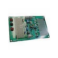
TC642EV
Description
KIT EVALUATION FOR TC642
Manufacturer
Microchip Technology
Specifications of TC642EV
Processor To Be Evaluated
TC642 and TC646
Lead Free Status / RoHS Status
Lead free / RoHS Compliant
Lead Free Status / RoHS Status
Lead free / RoHS Compliant, Lead free / RoHS Compliant
Other names
Q698359


TC64X/TC64XB Fan Control Evaluation Board User’s Guide
2.3
DS21403C-page 8
OPERATION IN THE ADJUSTABLE OUTPUT VOLTAGE MODE
2.3.1
Transistors such as 2N2222A are recommended for use as the output driver. These
transistors are low cost, multiple sourced and have a high enough Beta for BDC fan
applications of 200 mA or less operating current. If a single transistor is used, care
must be taken to select a transistor having a minimum h
minimum output current specification (5 mA) of the TC64X and TC64XB devices are
not exceeded. For large BDC fans, a logic level MOSFET is a good choice for the drive
device. All component selections should be made based on information in the
“Applications” section of the TC64X and TC64XB data sheets.
Table 2-2 provides a list of typical fan module operating configurations for 12V fan
applications. The values in Table 2-2 assume the use of low-cost, bipolar transistors
(such as the 2N2222A).
Substituting a logic level MOSFET, such as a BS170, for Q
voltage losses and significantly reduces output loading on the TC64X and TC64XB
devices. The low R
used in place of the Darlington in high current fan applications (See the TC64X and
TC64XB individual data sheets’ “Applications” section for details). The pinout of many
logic level MOSFETs is reversed from that of bipolar junction transistors, so care must
be taken to properly orient the MOSFET.
TABLE 2-2:
2.3.2
The TC64X and TC64XB data sheets provide detailed information relating to the
design of a temperature sensor based on a low cost thermistor.
Full Speed Fan
50 mA
100 mA
150 mA
200 mA
200 mA
250 mA
300 mA
350 mA
400 mA
450 mA
*R
Motor Current
2
is not necessary when using a MOSFET as the drive device.
Output Driver
Sensor Interface Circuit
OUTPUT DRIVE DEVICE CONFIGURATIONS
Pair/MOSFET*
DSON
Darlington
—
—
—
—
X
X
X
X
X
X
of the MOSFET (1 in the case of the BS170) enables it to be
Transistor
Single
—
—
—
—
—
—
X
X
X
X
2.4 k
1.1 k
5.6 k
4.7 k
3.9 k
3.0 k
2.4 k
3.3 k
750
620
( )
R
FE
2
2
of 50 to ensure that the
, results in lower system
2003 Microchip Technology Inc.
( )
1.5
9.1
4.7
3.0
2.4
2.4
2.0
1.8
1.3
1.2
R
3
Related parts for TC642EV
Image
Part Number
Description
Manufacturer
Datasheet
Request
R

Part Number:
Description:
DEMO BOARD FOR TC642/46/47/48/49
Manufacturer:
Microchip Technology
Datasheet:

Part Number:
Description:
Manufacturer:
Microchip Technology Inc.
Datasheet:
Part Number:
Description:
Manufacturer:
Microchip Technology Inc.
Datasheet:
Part Number:
Description:
Manufacturer:
Microchip Technology Inc.
Datasheet:
Part Number:
Description:
Manufacturer:
Microchip Technology Inc.
Datasheet:
Part Number:
Description:
Manufacturer:
Microchip Technology Inc.
Datasheet:
Part Number:
Description:
Manufacturer:
Microchip Technology Inc.
Datasheet:
Part Number:
Description:
Manufacturer:
Microchip Technology Inc.
Datasheet:
Part Number:
Description:
Manufacturer:
Microchip Technology Inc.
Datasheet: