DM163012 Microchip Technology, DM163012 Datasheet - Page 42
DM163012
Manufacturer Part Number
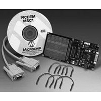
DM163012
Description
BOARD DEMO PICDEM FOR 16C781/782
Manufacturer
Microchip Technology
Datasheet
1.DM163012.pdf
(44 pages)
Specifications of DM163012
Supported Devices
PIC16C781/782
Interface Type
Serial
Processor To Be Evaluated
PIC16C781/782
For Use With
PIC16C781/782
Lead Free Status / RoHS Status
Contains lead / RoHS non-compliant
Lead Free Status / RoHS Status
Contains lead / RoHS non-compliant


PICDEM™ MSC1 User’s Guide
DS41178A-page 38
A 40-pin header between the PIC16C782 and the prototype area is intended
for jumpering prototype circuitry to the PIC16C782 or expanding the prototype
area by plugging a pre-made circuit onto the evaluation board. The V
AV
cuit and prototype areas. Removal of these jumpers allows for supply volt-
ages and capacity other than that provided by the on-board five volt
regulators. The RS-232 interface is two lines, asynchronous without hand-
shaking. Connection to the PC is via a 9-pin subminiature D connector, wired
for a standard 9-conductor serial port cable.
EVALUATION BOARD FIRMWARE
The Evaluation Board firmware is a simple monitor program that provides
read access to any of the PIC16C781/782 Special Function and memory data
registers or program locations. The firmware also provides write access to
any of the Special Function and data registers. The RS-232 interface is "bit-
banged," since the PIC16C781/782 does not contain a USART peripheral.
Immediately after a RESET, the firmware enters a Search mode for baud rate
calibration. The first character must be a ten-bit serial sequence composed of:
This is equivalent to sending a H’80’ character from a serial port set up for:
You can communicate with the PICDEM™ MSC1 Evaluation Board directly
from a PC with a hyperterminal window setup as just described with a baud
rate of 9600 or less, and local echo turned off. Immediately after the Evalua-
tion Board Reset, send the calibration character from the hyperterminal win-
dow by typing <Alt>(0128). In other words, hold down the <Alt> key down
while typing the four Key Pad numbers 0, 1, 2, 8 in sequence, then release
the <Alt> key. The Num Lock function must be enabled and the Key Pad num-
bers must be used instead of the number keys at the top of the keyboard.
Confirm proper calibration by typing the <Enter> key. The Evaluation Board
will respond with the ’>’ character. All characters are echoed by the Evaluation
Board firmware. Only those sequences corresponding to an actual command
will be processed. See the MONITOR.ASM file for details about the command
protocol. Baud rate recalibration can be remotely requested by sending a
break character that is at least three times the character time of the most
recent calibration.
A Break can be sent from the Hyperterminal by typing <CTRL><BREAK>
together.
Note:
DD
• Start bit (zero)
• Seven consecutive data zeros
• A one data bit
• A stop bit (one).
• Eight data bits
• One start bit
• One stop bit
• No parity.
jumpers connect the on-board linear regulators to the PIC16C782 cir-
The A
internal supply is the primary power source.
VDD
and V
DD
jumpers must be in place as shown when the
2001 Microchip Technology Inc.
DD
and
Related parts for DM163012
Image
Part Number
Description
Manufacturer
Datasheet
Request
R

Part Number:
Description:
Manufacturer:
Microchip Technology Inc.
Datasheet:
Part Number:
Description:
Manufacturer:
Microchip Technology Inc.
Datasheet:
Part Number:
Description:
Manufacturer:
Microchip Technology Inc.
Datasheet:
Part Number:
Description:
Manufacturer:
Microchip Technology Inc.
Datasheet:
Part Number:
Description:
Manufacturer:
Microchip Technology Inc.
Datasheet:
Part Number:
Description:
Manufacturer:
Microchip Technology Inc.
Datasheet:
Part Number:
Description:
Manufacturer:
Microchip Technology Inc.
Datasheet:
Part Number:
Description:
Manufacturer:
Microchip Technology Inc.
Datasheet: