PS042 Microchip Technology, PS042 Datasheet - Page 4
PS042
Manufacturer Part Number
PS042
Description
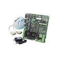
BOARD PWR CALIBRATION FOR PS401
Manufacturer
Microchip Technology
Specifications of PS042
Processor To Be Evaluated
PS 40X family
Interface Type
RS-232, RS-485
Lead Free Status / RoHS Status
Lead free / RoHS Compliant
Lead Free Status / RoHS Status
Lead free / RoHS Compliant, Lead free / RoHS Compliant


PS042
3.0
With the current firmware, the PowerCal board can
perform programming and test of packs and modules
and the calibration of pack and cell voltages on packs.
Apply power (24V DC) to the board at either the JP
connector using an A/C wall adapter, or at TBP
connector. To use a single PowerCal board connected
to the serial port of a PC, configure the COM and RX
jumpers for RS-232 and connect the P1 connector to
the PC serial port. To use multiple boards per COM
port, configure the COM and RX jumpers for RS-485
and connect the P1 connector to the RS-485 connector
on the PC card. Additional PowerCal boards may be
added by connecting J1 on the first board, to P1 on the
next, using a standard (straight-through) PC serial
cable. Up to seven boards may be added in this
manner. Use the ADR jumper to give each board a
unique address. Install and run Microchip’s PowerTool
software on the PC. The calibration platform is ready to
use.
DS40237B-page 4
FUNCTIONAL DESCRIPTION
3.1
Attach the external pack contacts of the Microchip
Smart Battery pack (V+, C, D, T, V-) to the same
terminals on the TBB connector. Using PowerTool
software, the EEPROM can be programmed and the
pack voltage can be calibrated. To program OTP
memory, the V
connected to V
connection is only necessary for OTP programming.
Additional PowerTool features, such as final test, can
also be performed on the pack.
3.2
Additional connections to the TBB connector are
necessary for the calibration of individual cell voltages.
The bottom of the cell stack is connected to V
of the cell stack is connected to V1, and the
intermediate cell connections are made from the top-
down. In other words, V2 is connected to the next cell
below V1, V3 below V2, and V4 below V3. For 3-cell
packs, short V4 to VR. For 2-cell packs, short V3 and
V4 to VR. PowerTool software is used to calibrate the
cell voltages.
Pack Programming, Calibration
and Test
V
CELL
PP
PP
Calibration
on the TBB connector. The additional
contact in the pack must be
2003 Microchip Technology Inc.
R
, the top
Related parts for PS042
Image
Part Number
Description
Manufacturer
Datasheet
Request
R

Part Number:
Description:
Manufacturer:
Microchip Technology Inc.
Datasheet:
Part Number:
Description:
Manufacturer:
Microchip Technology Inc.
Datasheet:
Part Number:
Description:
Manufacturer:
Microchip Technology Inc.
Datasheet:
Part Number:
Description:
Manufacturer:
Microchip Technology Inc.
Datasheet:
Part Number:
Description:
Manufacturer:
Microchip Technology Inc.
Datasheet:
Part Number:
Description:
Manufacturer:
Microchip Technology Inc.
Datasheet:
Part Number:
Description:
Manufacturer:
Microchip Technology Inc.
Datasheet:
Part Number:
Description:
Manufacturer:
Microchip Technology Inc.
Datasheet: