AD8332-EVAL Analog Devices Inc, AD8332-EVAL Datasheet - Page 28
AD8332-EVAL
Manufacturer Part Number
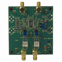
AD8332-EVAL
Description
BOARD EVAL FOR AD8332
Manufacturer
Analog Devices Inc
Specifications of AD8332-EVAL
Lead Free Status / RoHS Status
Contains lead / RoHS non-compliant


AD8331/AD8332/AD8334
The gain slope can be inverted, as shown in Figure 73 (except
for the AD8332 AR models). The gain drops with a slope of
−50 dB/V across the gain control range from maximum to
minimum gain. This slope is useful in applications such as
automatic gain control, where the control voltage is propor-
tional to the measured output signal amplitude. The inverse
gain mode is selected by setting the MODE pin to HI gain mode.
Gain control response time is less than 750 ns to settle within 10%
of the final value for a change from minimum to maximum gain.
VGA Noise
In a typical application, a VGA compresses a wide dynamic
range input signal to within the input span of an ADC. While
the input-referred noise of the LNA limits the minimum resolvable
input signal, the output-referred noise, which depends primarily
on the VGA, limits the maximum instantaneous dynamic range
that can be processed at any one particular gain control voltage.
This limit is set in accordance with the quantization noise floor
of the ADC.
Output and input-referred noise as a function of V
in Figure 25 and Figure 27 for the short-circuited input condi-
tions. The input noise voltage is simply equal to the output noise
divided by the measured gain at each point in the control range.
The output-referred noise is flat over most of the gain range
because it is dominated by the fixed output-referred noise of the
VGA. Values are 48 nV/√Hz in LO gain mode and 178 nV/√Hz
in HI gain mode. At the high end of the gain control range, the
noise of the LNA and the noise of the source prevail. The input-
referred noise reaches its minimum value near the maximum
gain control voltage, where the input-referred contribution of
the VGA becomes very small.
At lower gains, the input-referred noise, and thus noise figure,
increases as the gain decreases. The instantaneous dynamic
range of the system is not lost, however, because the input
capacity increases with it. The contribution of the ADC noise
floor has the same dependence as well. The important
relationship is the magnitude of the VGA output noise floor
relative to that of the ADC.
With its low output-referred noise levels, these devices ideally
drive low voltage ADCs. The converter noise floor drops 12 dB
for every two bits of resolution and drops at lower input full-
scale voltages and higher sampling rates. ADC quantization
noise is discussed in the Applications Information section.
The preceding noise performance discussion applies to a
differential VGA output signal. Although the LNA noise
performance is the same in single-ended and differential
applications, the VGA performance is not. The noise of the
VGA is significantly higher in single-ended usage because the
contribution of its bias noise is designed to cancel in the differential
signal. A transformer can be used with single-ended applications
when low noise is desired.
GAIN
are plotted
Rev. F | Page 28 of 60
Gain control noise is a concern in very low noise applications.
Thermal noise in the gain control interface can modulate the
channel gain. The resultant noise is proportional to the output
signal level and usually only evident when a large signal is
present. Its effect is observable only in LO gain mode where the
noise floor is substantially lower. The gain interface includes an
on-chip noise filter, which reduces this effect significantly at
frequencies above 5 MHz. Care should be taken to minimize
noise impinging at the GAIN input. An external RC filter can be
used to remove V
sufficient to accommodate the desired control bandwidth.
Common-Mode Biasing
An internal bias network connected to a midsupply voltage
establishes common-mode voltages in the VGA and postamp.
An externally bypassed buffer maintains the voltage. The bypass
capacitors form an important ac ground connection because the
VCM network makes a number of important connections
internally, including the center tap of the VGA differential input
attenuator, the feedback network of the VGA fixed gain
amplifier, and the feedback network of the postamp in both
gain settings. For best results, use a 1 nF capacitor and a 0.1 μF
capacitor in parallel, with the 1 nF capacitor nearest to the VCM
pin. Separate VCM pins are provided for each channel. For dc
coupling to a 3 V ADC, the output common-mode voltage is
adjusted to 1.5 V by biasing the VCM pin.
POSTAMPLIFIER
The final stage has a selectable gain of 3.5 dB (×1.5) or 15.5 dB
(×6), set by the HILO logic pin. Figure 79 is a simplified block
diagram.
Separate feedback attenuators implement the two gain settings.
These are selected in conjunction with an appropriately scaled
input stage to maintain a constant 3 dB bandwidth between the
two gain modes (~150 MHz). The slew rate is 1200 V/μs in HI
gain mode and 300 V/μs in LO gain mode. The feedback
networks for HI and LO gain modes are factory trimmed to
adjust the absolute gains of each channel.
VCM
+
–
Figure 79. Postamplifier Block Diagram
GAIN
source noise. The filter bandwidth should be
Gm1
Gm2
Gm1
Gm2
F1
F2
VOH
VOL
Related parts for AD8332-EVAL
Image
Part Number
Description
Manufacturer
Datasheet
Request
R

Part Number:
Description:
BOARD EVAL FOR AD8332
Manufacturer:
Analog Devices Inc
Datasheet:

Part Number:
Description:
±1.7g Dual-Axis IMEMS Accelerometer Evaluation Board
Manufacturer:
Analog Devices Inc
Datasheet:

Part Number:
Description:
Inertial Sensor Evaluation System
Manufacturer:
Analog Devices Inc
Datasheet:
Part Number:
Description:
Manufacturer:
Analog Devices Inc
Datasheet:
Part Number:
Description:
Manufacturer:
Analog Devices Inc
Datasheet:
Part Number:
Description:
Manufacturer:
Analog Devices Inc
Datasheet:
Part Number:
Description:
Manufacturer:
Analog Devices Inc
Datasheet:
Part Number:
Description:
Manufacturer:
Analog Devices Inc
Datasheet:
Part Number:
Description:
Manufacturer:
Analog Devices Inc
Datasheet:
Part Number:
Description:
Manufacturer:
Analog Devices Inc
Datasheet:
Part Number:
Description:
Manufacturer:
Analog Devices Inc
Datasheet:
Part Number:
Description:
Manufacturer:
Analog Devices Inc
Datasheet:
Part Number:
Description:
Manufacturer:
Analog Devices Inc
Datasheet: