AD1836A-DBRD Analog Devices Inc, AD1836A-DBRD Datasheet - Page 10
AD1836A-DBRD
Manufacturer Part Number
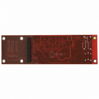
AD1836A-DBRD
Description
BOARD EVAL FOR AD1836A
Manufacturer
Analog Devices Inc
Specifications of AD1836A-DBRD
Module/board Type
Evaluation Board
Lead Free Status / RoHS Status
Contains lead / RoHS non-compliant
For Use With/related Products
AD1836A
Lead Free Status / RoHS Status
Not Compliant, Contains lead / RoHS non-compliant


AD1836A
Pin No.
27
28
29
30
31
32
33
34
35
36
37
38
39
40
41
42
43
44
45
46
47
48
49
50
51
52
In/Out
I
I
I
O
O
O
O
O
O
I/O
I/O
I
I
I
I
I
O
O
I
I
O
O
O
I
I
I
Mnemonic
ADC2INRP/CAPR2
AGND
AGND
OUTRN1
OUTRP1
OUTRN2
OUTRP2
OUTRN3
OUTRP3
DLRCLK
DBCLK
DSDATA1
DGND
DVDD
DSDATA2
DSDATA3
ABCLK
ALRCLK
MCLK
ODVDD
ASDATA1
ASDATA2
COUT
CLATCH
CCLK
DGND
Description
ADC2 Right Positive Input (Direct Mode)/ADC2 Right Decoupling Capacitor
(MUX/PGA and PGA Differential Mode).
Analog Ground.
Analog Ground.
DAC 1 Right Negative Output.
DAC 1 Right Positive Output.
DAC 2 Right Negative Output.
DAC 2 Right Positive Output.
DAC 3 Right Negative Output.
DAC 3 Right Positive Output.
LR Clock for DACs.
Bit Clock for DACs.
DAC Input 1 (Input to DAC 1 L and R).
Digital Ground.
Digital Power Supply. Connect to digital 5 V supply.
DAC Input 2 (Input to DAC 2 L and R).
DAC Input 3 (Input to DAC 3 L and R).
Bit Clock for ADCs.
LR Clock for ADCs.
Master Clock Input.
Digital Output Driver Power Supply. Connect to 3.3 V or 5 V logic supply.
ADC Serial Data Output 1 (ADC 1 L and R).
ADC Serial Data Output 2 (ADC 2 L and R).
Output for Control Data.
Latch Input for Control Data.
Control Clock Input for Control Data.
Digital Ground.
Rev. 0 | Page 10 of 24
Related parts for AD1836A-DBRD
Image
Part Number
Description
Manufacturer
Datasheet
Request
R


Part Number:
Description:
±1.7g Dual-Axis IMEMS Accelerometer Evaluation Board
Manufacturer:
Analog Devices Inc
Datasheet:

Part Number:
Description:
Inertial Sensor Evaluation System
Manufacturer:
Analog Devices Inc
Datasheet:
Part Number:
Description:
Manufacturer:
Analog Devices Inc
Datasheet:
Part Number:
Description:
Manufacturer:
Analog Devices Inc
Datasheet:
Part Number:
Description:
Manufacturer:
Analog Devices Inc
Datasheet:
Part Number:
Description:
Manufacturer:
Analog Devices Inc
Datasheet:
Part Number:
Description:
Manufacturer:
Analog Devices Inc
Datasheet:
Part Number:
Description:
Manufacturer:
Analog Devices Inc
Datasheet:
Part Number:
Description:
Manufacturer:
Analog Devices Inc
Datasheet:
Part Number:
Description:
Manufacturer:
Analog Devices Inc
Datasheet:
Part Number:
Description:
Manufacturer:
Analog Devices Inc
Datasheet:
Part Number:
Description:
Manufacturer:
Analog Devices Inc
Datasheet: